FORM 150.65-NM4
65
YORK INTERNATIONAL
Anticipation safeties monitor suction and discharge pres-
sure and unload the compressors as needed. The micro
will display a message on the STATUS DISPLAY when-
ever these controls are in operation.
CURRENT LIMITING
If current exceeds the value programmed by the user
(Page 45), the micro will unload the affected compressor.
Whenever Current Limiting is activated, the compressor
will stay in the unloaded state for 5 minutes. After the 5
minute time period, the micro will look at motor current
once again. If motor is 25% below the programmed Mo-
tor Current Unload point, the compressor will be allowed
to reload, if water temperature allows.
This safety assures that the motor will receive proper
cooling from the refrigerant which promotes longer motor
life.
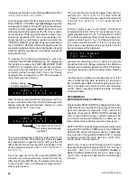
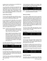
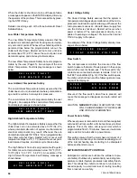
An example of the message displayed when current lim-
iting is in effect is shown below:
Discharge Pressure Unloading
If the discharge pressure exceeds the value programmed
by the user (Page 44), the micro will unload the affected
compressor. Automatic reloading will occur when pres-
sure drops 60 PSI below the programmed value. This
feature reduces the chance of faulting on the high dis-
charge pressure cut-out.
On water cooled chillers, this safety reduces the chance
of tripping the relief valve due to a very high rate of rise in
pressure resulting from a controls problem which would
cause condenser water flow to be interrupted. In this
case, the pressure rise is so fast, refrigerant loss may
occur through the relief valve even though the high pres-
sure cut-out has opened and the compressor is in the
midst of stopping.
An example of the message displayed when discharge
pressure unloadings in effect is shown below:
INTERNAL TIMERS AND PUMPDOWN CONTROLS
ANTI-RECYCLE TIMER
Anytime a compressor shuts down for any reason, re-
start cannot occur until the programmable Anti-recycle
Timer (Page 45) has timed out (timer starts with the com-
pressor start). Even though the Anti-recycle timer has
timed out, a minimum of 2 minutes (2-minute start-up
timer) must always elapse after a compressor stop be-
fore it may again restart.
If a power failure occurs, the anti-recycle timers will re-
set to 2 minutes after power is re-applied.
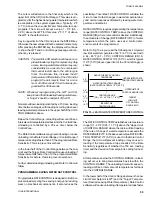
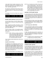
If the anti-recycle timer is preventing a start, the timer
position in seconds may be viewed by pressing the STA-
TUS key. A sample display is shown below.
ANTI-COINCIDENCE TIMER
The Anti-Coincidence Timer assures that 2 compressors
can never start simultaneously. This assures that ex-
cessive current demand will never result. A one minute
time delay will always separate compressor starts.
The Anti-Coincidence Timer can be viewed, when it is
active, by pressing the STATUS key. A sample display
is shown below.
PUMPDOWN CONTROLS
Pumpdown control will pump down a system to the suc-
tion pressure cut-out whenever the compressor shuts
down on a normal shutdown. Additionally, a recycling
pumpdown is employed on an as needed basis to as-
sure that liquid does not accumulate in the evaporator
on an OFF system, while cold chilled liquid is flowing,
through the evaporator. Since pumpdown at start-up is
not employed, the liquid line solenoid valve will open
immediately when a compressor starts.
“Pumpdown on shutdown” will pump a system down
whenever a system shuts down, except in two circum-
stances. A pumpdown will not occur whenever a fault
causes a shutdown or when “UNIT” rocker switch is
turned off. Pumpdown will continue until the suction pres-
sure falls below the suction pressure cut-out. If the pres-
sure never drops below the cut-out, pumpdown will con-
tinue until a 3-minute pumpdown timer has expired.
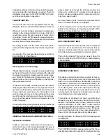
During pumpdown, the following STATUS message will
be displayed:
The PUMPING DOWN message indicates that the re-
spective compressor is presently in the process of pump-
S Y S # 1
D S C H
L I M I T I N G
S Y S # 2
D S C H
L I M I T I N G
S Y S # 1
A R
T M R
1 0 2
S
S Y S # 2
A R
T M R
1 0 2
S
S Y S # 1
C O M P
R U N N I N G
S Y S # 1
A C
T M R
5 6
S
S Y S # 1
C U R R
L I M I T I N G
S Y S # 2
C U R R
L I M I T I N G
S Y S # 1
P U M P I N G
D O W N
S Y S # 2
P U M P I N G
D O W N
Содержание Millennium YCAJ150
Страница 21: ...FORM 150 65 NM4 21 YORK INTERNATIONAL LD02461 FIG 6 ELEMENTARY DIAGRAM Cont d...
Страница 22: ...22 YORK INTERNATIONAL ELEMENTARY DIAGRAM...
Страница 24: ...24 YORK INTERNATIONAL CONNECTION DIAGRAM FIG 7 CONNECTION DIAGRAM LD02463...
Страница 25: ...FORM 150 65 NM4 25 YORK INTERNATIONAL FIG 7 CONNECTION DIAGRAM Cont d LD02462...
Страница 26: ...26 YORK INTERNATIONAL CONNECTION DIAGRAM TERMINAL BOX AND SYSTEM WIRING FIG 8 SYSTEM WIRING LD02464...
Страница 28: ...28 YORK INTERNATIONAL CONNECTION DIAGRAM TERMINAL BOX AND SYSTEM WIRING FIG 8 SYSTEM WIRING Cont d LD02650...
Страница 30: ...30 YORK INTERNATIONAL FIG 8 SYSTEM WIRING Cont d LD02499...
Страница 100: ...100 YORK INTERNATIONAL LD02654 FIG 37B LOUVER BRACKETS INSTALLATION...
Страница 101: ...FORM 150 65 NM4 101 YORK INTERNATIONAL LD02655 FIG 37C GRILLE AND LOUVER INSTALLATION FRONT AND BACK...
Страница 103: ...FORM 150 65 NM4 103 YORK INTERNATIONAL LD02656 FIG 39A LOUVER INSTALLATION SIDES...
Страница 104: ...104 YORK INTERNATIONAL LD02654 FIG 39B LOUVER BRACKETS INSTALLATION...
Страница 105: ...FORM 150 65 NM4 105 YORK INTERNATIONAL LD02657 FIG 39C GRILLE AND LOUVER INSTALLATION FRONT AND BACK...
Страница 107: ...FORM 150 65 NM4 107 YORK INTERNATIONAL FIG 40A CONDENSER COIL LOUVER INSTALLATION SIDES LD02658...
Страница 108: ...108 YORK INTERNATIONAL FIG 40B CONDENSER COIL LOUVER INSTALLATION FRONT AND BACK LD02659...
Страница 110: ...110 YORK INTERNATIONAL FIG 41 REMOTE RESET BOARD LD02666 P1...


