


FORM 150.65-NM4
43
YORK INTERNATIONAL
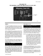
DISCHARGE CUT-OUT
The DISCHARGE CUT-OUT is a microprocessor backup
for the mechanical high pressure cut-out located in each
refrigerant circuit. Typically chillers with air-cooled con-
densers should have the cut-out set at 395 PSIG (2.7
mPa). Chillers with water-cooled condensers normal re-
quire the cut-out to be set at 275 PSIG (1.9 mPa).
NOTE: In some water cooled condenser installations,
the possibility exists for the condenser water
pump or the cooling tower to not be in operation
when the chiller starts. This causes the dis-
charge pressure to rise so rapidly that even
though the mechanical high pressure cut-out is
shutting down the compressor, the flywheel ef-
fect may cause the pressure to continue to rise
causing the relief valve to open with a subse-
quent refrigerant loss. By programming the cut-
out at the typical manual cut-out at 275 PSIG
(1.9 mPa), refrigerant loss due to system op-
eration problems will be eliminated.
To program the DISCHARGE CUT-OUT, key in the de-
sired value and press the ENTER key. The new value will
be entered into memory and the display will advance to
the next user programmable limit.
The micro will accept a range of programmable values
between 200 - 399 PSIG (1.4 - 2.8 mPa) for this cut-out.
For this cut-out to be functional, the Discharge Pressure
Readout Option must be installed.
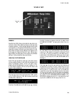
GENERAL
Pushing the PROGRAM key allows the user to program
“11” system operating limits. These limits include cutout
points for safeties, anti-recycle timer duration, and the
reaction time of the microprocessor to abrupt changes
in the chilled water temperatures.
After the PROGRAM key is pressed, the micro will first
respond by displaying the DISCHARGE CUT-OUT. As
the “11” limits are displayed, they may be reprogrammed
using the “12” ENTRY keys. New values will be pro-
grammed into memory when the ENTER key is pushed.
The ENTER key must also be used to advance the dis-
play the operator views the “10” system operating limits.
Each time the key is pushed, the display will advance to
the next limit.
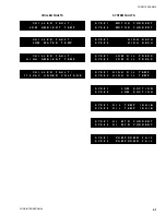
If the operator attempts to enter an unacceptable value,
the micro will respond with a momentary message indi-
cating the value selected has been ignored. This error
message is shown:
The “11” programmable limit displays are shown and
described below along with the range of values which
the microprocessor will accept for each limit.
THESE
VALUES MUST BE CHECKED AND PROPERLY PRO-
GRAMMED WHEN COMMISSIONING THE CHILLER.
FAILURE TO PROPERLY PROGRAM THESE VALUES
MAY CAUSE DAMAGE TO THE CHILLER OR OPERA-
TION PROBLEMS.
Photo #
“PROGRAM” KEY
PROGRAMMING USER PROGRAMMABLE SAFETIES AND LIMITS
“PROGRAM”
KEY
O U T
O F
R A N G E
T R Y
A G A I N !
D I S C H A R G E
C U T O U T
=
3 9 5
P S I G
02711TG
Содержание Millennium YCAJ150
Страница 21: ...FORM 150 65 NM4 21 YORK INTERNATIONAL LD02461 FIG 6 ELEMENTARY DIAGRAM Cont d...
Страница 22: ...22 YORK INTERNATIONAL ELEMENTARY DIAGRAM...
Страница 24: ...24 YORK INTERNATIONAL CONNECTION DIAGRAM FIG 7 CONNECTION DIAGRAM LD02463...
Страница 25: ...FORM 150 65 NM4 25 YORK INTERNATIONAL FIG 7 CONNECTION DIAGRAM Cont d LD02462...
Страница 26: ...26 YORK INTERNATIONAL CONNECTION DIAGRAM TERMINAL BOX AND SYSTEM WIRING FIG 8 SYSTEM WIRING LD02464...
Страница 28: ...28 YORK INTERNATIONAL CONNECTION DIAGRAM TERMINAL BOX AND SYSTEM WIRING FIG 8 SYSTEM WIRING Cont d LD02650...
Страница 30: ...30 YORK INTERNATIONAL FIG 8 SYSTEM WIRING Cont d LD02499...
Страница 100: ...100 YORK INTERNATIONAL LD02654 FIG 37B LOUVER BRACKETS INSTALLATION...
Страница 101: ...FORM 150 65 NM4 101 YORK INTERNATIONAL LD02655 FIG 37C GRILLE AND LOUVER INSTALLATION FRONT AND BACK...
Страница 103: ...FORM 150 65 NM4 103 YORK INTERNATIONAL LD02656 FIG 39A LOUVER INSTALLATION SIDES...
Страница 104: ...104 YORK INTERNATIONAL LD02654 FIG 39B LOUVER BRACKETS INSTALLATION...
Страница 105: ...FORM 150 65 NM4 105 YORK INTERNATIONAL LD02657 FIG 39C GRILLE AND LOUVER INSTALLATION FRONT AND BACK...
Страница 107: ...FORM 150 65 NM4 107 YORK INTERNATIONAL FIG 40A CONDENSER COIL LOUVER INSTALLATION SIDES LD02658...
Страница 108: ...108 YORK INTERNATIONAL FIG 40B CONDENSER COIL LOUVER INSTALLATION FRONT AND BACK LD02659...
Страница 110: ...110 YORK INTERNATIONAL FIG 41 REMOTE RESET BOARD LD02666 P1...