


FORM 150.65-NM4
77
YORK INTERNATIONAL
EMS/BAS CONTROLS
The microprocessor is capable of REMOTE START/
STOP, REMOTE UNLOADING (Pulldown demand limit-
ing), and REMOTE SETPOINT RESET. These functions
can be easily utilized by connecting user supplied “dry”
contacts to the terminals on the TB3 Terminal Block.
REMOTE START/STOP BY A CYCLING DEVICE OR
TIME CLOCK
Remote START/STOP is accomplished by connecting a
time clock or other “dry” contact in series with the flow
switch on terminals 13 & 14. See Fig. 12 for the location
of the terminals. The contact must be closed to allow
the chiller to run. Any time the contact opens, the chiller
will shut down and the following status message will be
displayed.
Wiring from these contacts should not exceed 25 ft. and
should be run in grounded conduit that does not carry
any wiring other than control wiring. Additionally, if an
inductive device (relay, contactor) is supplying these
contacts, the coil of the device must be suppressed with
a user supplied YORK P/N 031-00808 suppressor.
REMOTE SETPOINT RESET
(REMOTE RESET TEMP RANGE)
Remote Setpoint Reset allows resetting the setpoint
upward from the programmed value in memory. This is
accomplished by connecting a “dry” contact between
terminals 13 & 17. See Fig. 12 for the location of these
terminals. Closing the contact for a defined period of time
allows reset of the setpoint upward by up to 40°F (22.2°C)
above the setpoint programmed in memory.
The maximum desired reset must be programmed into
memory and can be a value of 02 to 40°F (1.1 - 22.2°C).
This value will vary according to the user’s requirements.
To program the reset, press the REMOTE SETPOINT
TEMP RANGE key. The following message will appear.
The display will indicate the REM SETPOINT which is
always equal to the chilled liquid setpoint plus the offset
from the reset signal. The display will also show the
REM RANGE which is the same as the maximum reset
required. Key in the maximum reset for the REM RANGE
and press the ENTER Key to store the new value in
memory.
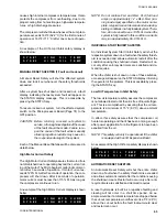
S Y S # 1
N O
R U N
P E R M
S Y S # 2
N O
R U N
P E R M
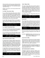
R E M
S E T P O I N T
=
4 0 . 0
R E M
R A N G E
=
2 0
D E G F
ing requirements. In addition, the low battery message
which is displayed for this condition will disappear.
NOTE: If a power failure should again occur, the above
process will again need to be repeated to bring
the chiller back on line.
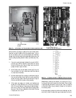
In the unlikely event the low battery message should
ever appear, it will require the RTC Chip U13 on the Mi-
croprocessor Board (Fig. 13 to be replaced. Care should
be taken to assure that the chip is properly installed.
Pin 1 (dimple in the top of the chip) must be oriented as
shown (Fig. 13. The part number for the RTC Chip is
031-00955-000.
CRANKCASE HEATER
The crankcase heater for a compressor will be ON when-
ever the compressor is not running. The heater is inter-
locked into the compressor motor contactor and is not
controlled by the microprocessor.
The purpose of the crankcase heater is to prevent the
migration of refrigerant to the crankcase during shutdown
assuring proper lubrication of the compressor on start-
up.
Anytime power is removed from the chiller for more than
an hour, the crankcase heater should be left on for 24
hours prior to start. This can be accomplished by apply-
ing 115VAC to the control panel.
EVAPORATOR HEATER
The evaporator heater prevents water standing in the
evaporator from freezing. Whenever outdoor ambient tem-
perature drops below 40°F (4.4°C), the microprocessor
will turn the evaporator ON. If temperature rises above
45°F (7.2°C) the heater will be turned off.
METRIC DISPLAY
The control panel is capable of providing displays of pres-
sure and temperature in metric values. Temperatures will
be displayed in °C and pressures in kPa.
A Metric to English temperature conversion table is pro-
vided on the rear cover of this manual. Pressure can be
converted from PSI to kPa using the formula PSI x 6.89
= kPa.
To obtain panel displays in metric, Switch 5 of Dip Switch
S1 on the Microprocessor Board must be placed in the
OPEN position (Page 37). The positioning of this switch
can then be verified by pushing the OPTIONS key and
verifying that “METRIC UNITS READOUT” is programmed
(Page 35).
Содержание Millennium YCAJ150
Страница 21: ...FORM 150 65 NM4 21 YORK INTERNATIONAL LD02461 FIG 6 ELEMENTARY DIAGRAM Cont d...
Страница 22: ...22 YORK INTERNATIONAL ELEMENTARY DIAGRAM...
Страница 24: ...24 YORK INTERNATIONAL CONNECTION DIAGRAM FIG 7 CONNECTION DIAGRAM LD02463...
Страница 25: ...FORM 150 65 NM4 25 YORK INTERNATIONAL FIG 7 CONNECTION DIAGRAM Cont d LD02462...
Страница 26: ...26 YORK INTERNATIONAL CONNECTION DIAGRAM TERMINAL BOX AND SYSTEM WIRING FIG 8 SYSTEM WIRING LD02464...
Страница 28: ...28 YORK INTERNATIONAL CONNECTION DIAGRAM TERMINAL BOX AND SYSTEM WIRING FIG 8 SYSTEM WIRING Cont d LD02650...
Страница 30: ...30 YORK INTERNATIONAL FIG 8 SYSTEM WIRING Cont d LD02499...
Страница 100: ...100 YORK INTERNATIONAL LD02654 FIG 37B LOUVER BRACKETS INSTALLATION...
Страница 101: ...FORM 150 65 NM4 101 YORK INTERNATIONAL LD02655 FIG 37C GRILLE AND LOUVER INSTALLATION FRONT AND BACK...
Страница 103: ...FORM 150 65 NM4 103 YORK INTERNATIONAL LD02656 FIG 39A LOUVER INSTALLATION SIDES...
Страница 104: ...104 YORK INTERNATIONAL LD02654 FIG 39B LOUVER BRACKETS INSTALLATION...
Страница 105: ...FORM 150 65 NM4 105 YORK INTERNATIONAL LD02657 FIG 39C GRILLE AND LOUVER INSTALLATION FRONT AND BACK...
Страница 107: ...FORM 150 65 NM4 107 YORK INTERNATIONAL FIG 40A CONDENSER COIL LOUVER INSTALLATION SIDES LD02658...
Страница 108: ...108 YORK INTERNATIONAL FIG 40B CONDENSER COIL LOUVER INSTALLATION FRONT AND BACK LD02659...
Страница 110: ...110 YORK INTERNATIONAL FIG 41 REMOTE RESET BOARD LD02666 P1...