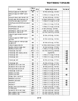
TIGHTENING TORQUES
2-19
• Engine mounting adjust bolt and engine mount self locking nut
Refer to "INSTALLING THE ENGINE" on page 5-7.
• Front wheel axle pinch bolt
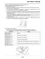
1. Insert the front wheel axle from the right side and tighten it with the flange bolt from the left
side to 91 Nm (9.1 m·kg, 65.8 ft·lb).
2. In the order from the pinch bolt “2”
→
pinch bolt “1”
→
pinch bolt “2”, tighten each bolt to 21 Nm
(2.1 m·kg, 15 ft·lb) without performing temporary tightening.
3. Check that the end face of the axle head and the end face of the fork side are flush-mounted.
If they are out of alignment, make sure to fit them by adding the external force by hand or with
a plastic hammer, etc.
If the end face of the axle is not parallel to the end face of the fork, align them so that one point
of the axle circumference is positioned on the end face of the fork.
At this stage, it can be accepted if the end face of the axle becomes partially concave to the
end face of the fork.
4. In the order from the pinch bolt “4”
→
pinch bolt “3”
→
pinch bolt “4”, tighten each bolt to 21 Nm
(2.1 m·kg, 15 ft·lb) without performing temporary tightening.
• Main frame and rear frame bolt
1. Check the clearance between rear frame and main frame by thickness gauge “1”.
Insert adjusting shim(s) to eliminate the gap according to the chart as shown below.
Shim: 0.5 mm (0.02 in)
Thickness
Shim(s)
Under 0.5 mm
(Under 0.01969 in)
NONE
0.51–1.0 mm
(0.02008–0.03937 in)
One shim on the left side
1.01–1.5 mm
(0.03976–0.05906 in)
Two shims on the left side
1.51–2.0 mm
(0.05945–0.07874 in)
Three shims on the left side
2.01–2.5 mm
(0.07913–0.09843 in)
Three shims on the left side and one shim on the right side
2.51–3.0 mm
(0.09882–0.11811 in)
Three shims on the left side and two shims on the right side
Содержание YZFR1W 2007
Страница 1: ...2007 MOTORCYCLE SERVICE MANUAL Model YZFR1W 4C8281972000 4C8281972000...
Страница 50: ...LUBRICATION POINTS AND LUBRICANT TYPES 2 22...
Страница 53: ...LUBRICATION SYSTEM CHART AND DIAGRAMS 2 25 EAS20410 LUBRICATION DIAGRAMS...
Страница 55: ...LUBRICATION SYSTEM CHART AND DIAGRAMS 2 27...
Страница 57: ...LUBRICATION SYSTEM CHART AND DIAGRAMS 2 29...
Страница 59: ...LUBRICATION SYSTEM CHART AND DIAGRAMS 2 31 A A A A...
Страница 60: ...LUBRICATION SYSTEM CHART AND DIAGRAMS 2 32 1 Main axle 2 Oil delivery pipe 3 Drive axle...
Страница 61: ...LUBRICATION SYSTEM CHART AND DIAGRAMS 2 33...
Страница 62: ...LUBRICATION SYSTEM CHART AND DIAGRAMS 2 34 1 Cylinder head 2 Crankshaft...
Страница 63: ...COOLING SYSTEM DIAGRAMS 2 35 EAS20420 COOLING SYSTEM DIAGRAMS...
Страница 64: ...COOLING SYSTEM DIAGRAMS 2 36 1 Water pump 2 Radiator 3 Radiator fan...
Страница 65: ...COOLING SYSTEM DIAGRAMS 2 37...
Страница 66: ...COOLING SYSTEM DIAGRAMS 2 38 1 Radiator cap 2 Radiator 3 Oil cooler 4 Thermostat...
Страница 67: ...CABLE ROUTING 2 39 EAS20430 CABLE ROUTING...
Страница 69: ...CABLE ROUTING 2 41...
Страница 71: ...CABLE ROUTING 2 43...
Страница 73: ...CABLE ROUTING 2 45...
Страница 75: ...CABLE ROUTING 2 47...
Страница 77: ...CABLE ROUTING 2 49...
Страница 79: ...CABLE ROUTING 2 51...
Страница 81: ...CABLE ROUTING 2 53...
Страница 171: ...HANDLEBARS 4 49...
Страница 197: ...CHAIN DRIVE 4 75...
Страница 200: ...CHECKING THE TRANSMISSION 5 90 INSTALLING THE TRANSMISSION 5 91...
Страница 292: ...TRANSMISSION 5 92 4 Check Transmission Rough movement Repair NOTE Oil each gear shaft and bearing thoroughly...
Страница 293: ...TRANSMISSION 5 93...
Страница 314: ...THROTTLE BODIES 7 8...
Страница 317: ...AIR INDUCTION SYSTEM 7 11...
Страница 320: ...IGNITION SYSTEM 8 1 EAS27090 IGNITION SYSTEM EAS27110 CIRCUIT DIAGRAM...
Страница 324: ...ELECTRIC STARTING SYSTEM 8 5 EAS27160 ELECTRIC STARTING SYSTEM EAS27170 CIRCUIT DIAGRAM...
Страница 330: ...CHARGING SYSTEM 8 11 EAS27200 CHARGING SYSTEM EAS27210 CIRCUIT DIAGRAM...
Страница 331: ...CHARGING SYSTEM 8 12 2 AC magneto 3 Rectifier regulator 4 Main fuse 8 Battery 88 Ground 89 Battery negative lead...
Страница 333: ...CHARGING SYSTEM 8 14...
Страница 334: ...LIGHTING SYSTEM 8 15 EAS27240 LIGHTING SYSTEM EAS27250 CIRCUIT DIAGRAM...
Страница 338: ...SIGNALING SYSTEM 8 19 EAS27270 SIGNALING SYSTEM EAS27280 CIRCUIT DIAGRAM...
Страница 344: ...COOLING SYSTEM 8 25 EAS27300 COOLING SYSTEM EAS27310 CIRCUIT DIAGRAM...
Страница 347: ...COOLING SYSTEM 8 28...
Страница 348: ...FUEL INJECTION SYSTEM 8 29 EAS27330 FUEL INJECTION SYSTEM EAS27340 CIRCUIT DIAGRAM...
Страница 384: ...FUEL PUMP SYSTEM 8 65 EAS27550 FUEL PUMP SYSTEM EAS27560 CIRCUIT DIAGRAM...
Страница 388: ...IMMOBILIZER SYSTEM 8 69 EAS27640 IMMOBILIZER SYSTEM EAS27650 CIRCUIT DIAGRAM...
Страница 396: ...ELECTRICAL COMPONENTS 8 77 EAS27970 ELECTRICAL COMPONENTS...
Страница 398: ...ELECTRICAL COMPONENTS 8 79...
Страница 400: ...ELECTRICAL COMPONENTS 8 81 EAS27980 CHECKING THE SWITCHES...
Страница 420: ...ELECTRICAL COMPONENTS 8 101...
Страница 429: ...Yamaha Motor Canada Ltd 480 Gordon Baker Road Toronto ON M2H 3B4...

