background image

ENG

4 - 93

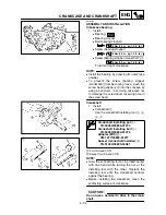
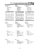
CARTER ET VILEBREQUIN

KURBELGEHÄUSE UND KURBELWELLE

CARTER E ALBERO MOTORE

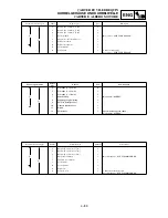
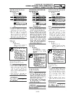
Kurbelwelle

1.

Messen:

Schlaggrenze 

a


Pleuel-Radialspiel 

b


Pleuel-Axialspiel 

c


Kurbelwangenbreite 

d


Unvorschriftsmäßig 


Erneuern.
Meßuhr und Fühlerlehre
verwenden.

Meßuhr und Ständer

YU-3097/90890-01252

Standard

<Grenz-

wert>

Schlag-

grenze

0,03 mm

0,05 mm

Pleuel-
Radial-

spiel

0,4–1,0 mm

2,0 mm

Pleuel-

Axial-

spiel

0,15–

0,45 mm

0,50 mm

Kurbel-

wangen-

breite

55,95–

56,00 mm

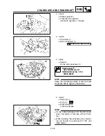
Ölsieb

1.

Kontrollieren:

Ölsieb
Beschädigung 

 Erneuern.

Ölzufuhrleitung 2

1.

Kontrollieren:

Ölzufuhrleitung 2 

1


O-Ring 

2


Beschädigung 

 Erneuern.

Ölzufuhrleitung 

a


Verstopfung 

 Ausblasen.

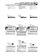
Vilebrequin

1.

Mesurer:

Limite de faux-rond 

a


Limite de déflexion de pied de
bielle 

b


Jeu latéral de tête de bielle 

c


Largeur de volant 

d


Hors spécification 

 Rempla-

cer.
Utiliser un comparateur à
cadran et une jauge d’épais-
seur.

Comparateur et support:

YU-3097/90890-01252

Standard

<Limite>

Limite de 

faux-

rond:

0,03 mm 

(0,0012 in)

0,05 mm

(0,002 in)

Déflexion 

de pied de 

bielle:

0,4 à 1,0 mm

(0,016 à 

0,039 in)

2,0 mm

(0,08 in)

Jeu laté-

ral:

0,15 à 

0,45 mm

(0,0059 à 

0,0177 in)

0,50 mm 

(0,02 in)

Largeur 

de volant:

55,95 à 

56,00 mm

(2,203 à 

2,205 in)

Crépine d’huile

1.

Contrôler:

Crépine d’huile
Endommagement 

 Rempla-

cer.

Tuyau d’arrivée d’huile 2

1.

Contrôler:

Tuyau d’arrivée d’huile 2 

1


Joint torique 

2


Endommagement 

 Rempla-

cer.

Orifices de tuyau d’arrivée
d’huile 

a


Bouché 

 Nettoyer.

Albero motore

1.

Misurare:

Limite di disassamento 

a


Limite gioco piede di biella 

b


Gioco laterale della testa di
biella 

c


Larghezza gomito 

d


Fuori specifica 

 Regolare.

Utilizzare un comparatore ed
uno spessimetro.

Comparatore e supporto:

YU-3097/90890-01252

Standard

<Limite>

Limite di 

disassa-

mento:

0,03 mm 

(0,0012 in)

0,05 mm 

(0,002 in)

Gioco 

piede di 

biella:

0,4 ~ 1,0 mm

(0,016 ~ 

0,039 in)

2,0 mm 

(0,08 in)

Gioco 

laterale:

0,15 ~ 

0,45 mm 

(0,0059 ~ 

0,0177 in)

0,50 mm 

(0,02 in)

Ampiezza 

incrina-

tura:

55,95 ~ 

56,00 mm 

(2,203 ~

2,205 in)

Filtro olio

1.

Ispezionare:

Filtro olio
Danni 

 Sostituire.

Tubazione alimentazione olio 2

1.

Ispezionare:

Tubazione alimentazione olio 2

1


O-ring 

2


Danni 

 Sostituire.

Orifizio dell’olio 

a


Intasato 

 Pulire con aria.

Содержание WR250F(P)

Страница 1: ...5PH 28199 31 WR250F P OWNER S SERVICE MANUAL MANUEL D ATELIER DU PROPRIETAIRE FAHRER UND WARTUNGS HANDBUCH MANUALE DI SERVIZIO DEL PROPRIETARIO...

Страница 2: ...S SERVICE MANUAL 2001 by Yamaha Motor Co Ltd 1st Edition September 2001 All rights reserved Any reprinting or unauthorized use without the written permission of Yamaha Motor Co Ltd is expressly prohi...

Страница 3: ...R DU PROPRIETAIRE 2001 Yamaha Motor Co Ltd 1 re dition septembre 2001 Tous droits r serv s Toute reimpression ou utillisation sans la permission crite de la Yamaha Motor Co Ltd est formellement interd...

Страница 4: ...lease contact your Yamaha dealer NOTE As improvements are made on this model some data in this manual may become out dated If you have any questions please con sult your Yamaha dealer WARNING PLEASE R...

Страница 5: ...sion naire Yamaha N B Comme des am liorations sont faites sur ce mod le quelques donn es contenues dans ce manuel peuvent tre p rim es Si vous avez des questions poser pri re de consulter votre conces...

Страница 6: ...PROTECTIVE APPAREL When operating this machine always wear an approved helmet with gog gles or a face shield Also wear heavy boots gloves and protective cloth ing Always wear proper fitting cloth ing...

Страница 7: ...e cette machine toujours porter un casque homologu avec des lunettes ou un prot ge visage Porter galement de grosses bottes des gants et des v te ments de protection Toujours porter des v tements de t...

Страница 8: ...Carbon monoxide is a dangerous gas which can cause unconscious ness or can be lethal 8 PARK THE MACHINE CAREFULLY TURN OFF THE ENGINE Always turn off the engine if you are going to leave the machine...

Страница 9: ...si vous devez abandonner la machine Ne pas stationner en pente ou sur un sol mou ou elle pourrait se renverser 9 LE MOTEUR LE SYST ME D CHAPPEMENT ET LE R SERVOIR D HUILE SONT TR S CHAUDS LORSQUE LE...

Страница 10: ...is machine and should remain with it even if the machine is subsequently sold EC060000 NOTICE Some data in this manual may become out dated due to improvements made to this model in the future If ther...

Страница 11: ...e machine veuillez consulter votre concessionnaire Yamaha N B Ce manuel doit tre consid r comme partie permanente de la machine et doit rester avec celle ci si elle est revendue une tierce personne AV...

Страница 12: ...avoid damage to the machine NOTE A NOTE provides key information to make pro cedures easier or clearer WARNING CAUTION EC082000 FINDING THE REQUIRED PAGE 1 This manual consists of seven chapters Gener...

Страница 13: ...eiten zu vereinfachen WARNUNG ACHTUNG INFORMATION AUFFINDEN 1 Diese Anleitung umfa t sieben Kapitel 1 Allgemeine Angaben 2 Technische Daten 3 Regelm ige Inspektionen und Einstellarbeiten 4 Motor 5 Fah...

Страница 14: ...start of each removal and disassembly section 1 An easy to see exploded diagram 1 is provided for removal and disassembly jobs 2 Numbers 2 are given in the order of the jobs in the exploded diagram A...

Страница 15: ...es en clat les pi ces sont num rot es 2 dans l ordre des op rations effectuer Un chiffre entour d un cercle correspond une tape de d montage 3 Les vues en clat portent gale ment des symboles 3 qui rap...

Страница 16: ...Lubricant B Tightening C Specified value Service limit D Resistance Voltage V Electric current A Illustrated symbols E to H in the exploded diagrams indicate grade of lubricant and loca tion of lubri...

Страница 17: ...nsit A Les symboles graphiques E H utilis s dans les vues en clat indiquent les endroit lubrifier et le type de lubrifiant E Appliquer de l huile moteur F Appliquer de l huile au bisulfure de moly bd...

Страница 18: ...EC090010 INDEX GENERAL INFORMATION SPECIFICATIONS REGULAR INSPECTION AND ADJUSTMENTS ENGINE CHASSIS ELECTRICAL TUNING...

Страница 19: ...PIANTO ELETTRICO ELEC 6 MESSA A PUNTO TUN 7 GEN INFO INSP ADJ INDEX RENSEIGNEMENTS GENERAUX CARACTERISTI QUES CONTROLES ET REGLAGES COURANTS MOTEUR PARTIE CYCLE PARTIE ELECTRIQUE MISES AU POINT INDEX...

Страница 20: ...TING AND BREAK IN 1 15 TORQUE CHECK POINTS 1 19 CLEANING AND STORAGE 1 20 CHAPTER 2 SPECIFICATIONS GENERAL SPECIFICATIONS 2 1 MAINTENANCE SPECIFICATIONS 2 4 GENERAL TORQUE SPECIFICATIONS 2 18 DEFINITI...

Страница 21: ...RIFICATION DE COUPLE DE SERRAGE 1 19 NETTOYAGE ET RANGEMENT 1 20 CHAPITRE 2 CARACTERISTIQUES CARACTERISTIQUES GENERALES 2 1 CARACTERISTIQUES D ENTRETIEN 2 4 CARACTERISTIQUES GENERALES DE COUPLE 2 18 D...

Страница 22: ...CH 4 50 OIL FILTER ELEMENT WATER PUMP AND RIGHT CRANKCASE COVER 4 57 BALANCER 4 64 OIL PUMP 4 67 KICK SHAFT AND SHIFT SHAFT 4 72 CDI MAGNETO 4 79 ENGINE REMOVAL 4 83 CRANKCASE AND CRANKSHAFT 4 88 TRAN...

Страница 23: ...DROIT 4 57 BALANCIER 4 64 POMPE A HUILE 4 67 ARBRE DE KICK ET ARBRE DE SELECTEUR 4 72 VOLANT MAGNETIQUE CDI 4 79 DEPOSE DU MOTEUR 4 83 CARTER ET VILEBREQUIN 4 88 BOITE A VITESSES TAMBOUR ET FOURCHETT...

Страница 24: ...R 6 ELECTRICAL ELECTRICAL COMPONENTS AND WIRING DIAGRAM 6 1 MAP CONTROLLED CDI UNIT 6 2 IGNITION SYSTEM 6 3 THROTTLE POSITION SENSOR SYSTEM 6 7 LIGHTING SYSTEM 6 12 CHAPTER 7 TUNING ENGINE 7 1 CHASSIS...

Страница 25: ...CABLAGE 6 1 BLOC CDI CONTROLE PAR MICROPROCESSEUR 6 2 SYSTEME D ALLUMAGE 6 3 CIRCUIT DU CAPTEUR DE PAPILLON DES GAZ 6 7 SYSTEME D ECLAIRAGE 6 12 CHAPITRE 7 MISES AU POINT MOTEUR 7 1 PARTIE CYCLE 7 12...

Страница 26: ...tank cap 0 Engine stop switch A Taillight B Kickstarter crank C Fuel tank D Headlight E Radiator F Coolant drain bolt G Rear brake pedal H Valve joint I Fuel cock J Cold starter knob K Hot starter kno...

Страница 27: ...ge du liquide de refroidissement G P dale de frein arri re H Joint de robinet I Robinet de carburant J Bouton de d marrage froid K Bouton de d marrage chaud rouge L Cha ne de transmission M Filtre air...

Страница 28: ...hine is stolen the authorities will need the number to search for and identify your machine EC121001 VEHICLE IDENTIFICATION NUMBER The vehicle identification number 1 is stamped on the right of the st...

Страница 29: ...O D IDENTIFICATION DU VEHICULE Le num ro d identification du v hicule 1 est frapp du c t droit du tube de direction NUMERO DE SERIE DU MOTEUR Le num ro de s rie du moteur 1 est estamp sur un bossage s...

Страница 30: ...bottom Carburetor accelerator pump 2 Use proper tools and cleaning equip ment Refer to SPECIAL TOOLS sec tion 3 When disassembling the machine keep mated parts together They include gears cylinders p...

Страница 31: ...ge correct Se reporter la section OUTILS SPECIAUX 3 Lors du d montage de la machine garder les pi ces conne xes ensemble Ils comprennent les engrenages cylindres pistons et autres pi ces connexes qui...

Страница 32: ...EC134000 LOCK WASHERS PLATES AND COTTER PINS 1 All lock washers plates 1 and cotter pins must be replaced when they are removed Lock tab s should be bent along the bolt or nut flat s after the bolt or...

Страница 33: ...freins d crou 1 et goupilles fendues ne doivent jamais tre r utilis s Les onglets de blocage doivent tre dress s contre les faces de boulon ou d crou une fois que les boulons et crous ont t correcteme...

Страница 34: ...uld be inspected carefully before reassembly Always replace pis ton pin clips after one use Replace dis torted circlips When installing a circlip 1 make sure that the sharp edged cor ner 2 is position...

Страница 35: ...circlips d axe de piston apr s une utilisa tion Changer tout circlip d form Lorsqu on monte un cir clip 1 s assurer que le c t non chanfrein 2 est positionn du c t oppos la pouss e 3 qu il re oit Voi...

Страница 36: ...check that it will not come off 5 If the terminal comes off bend up the pin 1 and reinsert the terminal into the con nector 6 Connect Connector NOTE The two connectors click together 7 Check for cont...

Страница 37: ...orne se d tache redresser la lame 1 de la broche et ins rer nouveau la borne dans le con necteur 6 Connecter Connecteur N B Les deux connecteurs s encliqu tent 7 V rifier la continuit avec un tes teur...

Страница 38: ...hen loosening or tightening the fly wheel magneto securing nut YU 1235 90890 01235 YU 3097 90890 01252 YU 1256 Dial gauge and stand Stand These tools are used to check each part for runout or bent YU...

Страница 39: ...tachometer Engine tachometer This tool is needed for observing engine rpm YU 8036 B 90890 03113 YM 33277 A 90890 03141 Timing light This tool is necessary for checking ignition timing YM 33277 A 90890...

Страница 40: ...ntake 4 0 mm 0 16 in Exhaust 4 5 mm 0 18 in This tool is needed to rebore the new valve guide YM 4113 YM 4118 90890 04113 90890 04118 YM 34487 90890 06754 Dynamic spark tester Ignition checker This in...

Страница 41: ...util est utilis pour le desserrage ou le serrage du boulon de fixation de volant magn tique YU 1235 90890 01235 YU 3097 90890 01252 YU 1256 Comparateur et support Support Ces outils permettent de cont...

Страница 42: ...pour observer la vitesse de rotation du moteur YU 8036 B 90890 03113 YM 33277 A 90890 03141 Lampe stroboscopique induction Cet outil est n cessaire pour v rifier le r glage de l allu mage YM 33277 A 9...

Страница 43: ...in Echappement 4 5 mm 0 18 in Cet outil est n cessaire pour r al ser le nouveau guide de soupape YM 4113 YM 4118 90890 04113 90890 04118 YM 34487 90890 06754 Testeur d tincelle dynamique Contr leur d...

Страница 44: ...und Befestigen des Schwungrad Magnetz nder Rotors YU 1235 90890 01235 YU 3097 90890 01252 YU 1256 Me uhr und St nder St nder Diese Werkzeuge dienen zum Pr fen der einzelnen Teile auf Unrundheit oder...

Страница 45: ...8036 B 90890 03113 Induktivdrehzahlmesser Motor Drehzahlmesser Zur Ermittlung der Motordrehzahl YU 8036 B 90890 03113 YM 33277 A 90890 03141 Stroboskoplampe Zur Kontrolle des Z ndzeitpunktes YM 33277...

Страница 46: ...hrungs Reibahle Einla 4 0 mm Ausla 4 5 mm Zum Aufreiben der neuen Ventilf hrungen YM 4113 YM 4118 90890 04113 90890 04118 YM 34487 90890 06754 Z ndfunkenstreckentester Z ndpr fer Zur berpr fung der Z...

Страница 47: ...avvita la vite di fissaggio del magnete del volano YU 1235 90890 01235 YU 3097 90890 01252 YU 1256 Comparatore e supporto Supporto Questi strumenti sono usati per controllare ciascuna parte per usura...

Страница 48: ...Questo strumento utilizzato per controllare la velocit del motore YU 8036 B 90890 03113 YM 33277 A 90890 03141 Lampada stroboscopica Questo strumento utilizzato per controllare la fasatura di accensi...

Страница 49: ...ttrezzo utilizzato per alesare il nuovo guidaval vola YM 4113 YM 4118 90890 04113 90890 04118 YM 34487 90890 06754 Tester della dinamicit della scintilla Tester dell accensione Questo attrezzo necessa...

Страница 50: ...h The lever should be pulled rapidly and released slowly for smooth starts EC153000 SHIFT PEDAL The gear ratios of the constant mesh 5 speed transmission are ideally spaced The gears can be shifted by...

Страница 51: ...er le levier d embrayage vers le guidon pour d brayer et rel cher le levier pour embrayer Pour des d mar rages doux le levier doit tre tir rapide ment et rel ch lentement PEDALE DE CHANGEMENT DE VITES...

Страница 52: ...he pressure in the cylinder head This enables the vehicle to be kickstarted more easily EC155001 THROTTLE GRIP The throttle grip 1 is located on the right han dlebar it accelerates or decelerates the...

Страница 53: ...de comprimer la soupape d chappement ce qui r duit la pression dans la culasse POIGNEE DES GAZ La poign e des gaz 1 est situ e la poi gn e droite elle permet d acc l rer ou de d c l rer le moteur Pou...

Страница 54: ...ET THE LEVER TO ON AFTER REFUELING COLD STARTER KNOB When cold the engine requires a richer air fuel mixture for starting A separate starter circuit which is controlled by the cold starter knob 1 supp...

Страница 55: ...ur a besoin d un m lange air essence plus riche pour le d marrage Un circuit de d marrage s par command par le bouton de de d marrage froid 1 fournit ce m lange Tirer le bouton de d marrage froid pour...

Страница 56: ...sure the arrow faces the fuel tank and also downward LIGHTS SWITCH The lights switch 1 is located on the handle bar FLAP In order to prevent water from entering the car buretor while the machine is o...

Страница 57: ...rs le r servoir d essence et le bas INTERRUPTEUR LUMIERES L interrupteur lumi res 1 est situ sur le guidon BAVETTE Pour viter toute p n tration d eau dans le carburateur pendant la conduite sous la pl...

Страница 58: ...use of leaded gasoline will cause severe damage to the engine internal parts such as valves piston rings and exhaust system etc NOTE If knocking or pinging occurs use a different brand of gasoline or...

Страница 59: ...ges aux parties internes du moteur valves segments de piston syst me d chappement etc Essence pr conis e Except pour ZA Essence super sans plomb d un indice d octane de recher che de 95 ou plus Pour Z...

Страница 60: ...use the decompression lever after the engine is started The engine may be damaged if you use the decompression lever while it is running Before starting the machine perform the checks in the pre opera...

Страница 61: ...vier de d compression lors que le moteur tourne risque d endommager ce dernier Avant la mise en marche effectuer les v rifications indiqu es dans la liste de contr le avant utilisation MISE EN MARCHE...

Страница 62: ...while kicking the kickstarter crank Otherwise the kick starter may kick back 8 Return the cold starter knob to its original position and run the engine at 3 000 5 000 r min for 1 or 2 minutes NOTE Si...

Страница 63: ...relever brutalement 8 Ramener le bouton de d marrage froid sa position d origine puis faire tourner le moteur 3 000 5 000 tr mn pendant 1 2 minutes N B Puisque ce mod le est quip d une pompe d acc l...

Страница 64: ...while holding the lever kick the kickstarter crank 10 to 20 times to clear the engine Then restart the engine Refer to Restarting an engine after a fall Operate the throttle grip before kick starting...

Страница 65: ...apr s une chute Donner des gaz avant d actionner le kick ATTENTION Dans un premier temps observer la proc dure de rodage suivante afin d assurer le meilleur rendement et viter d endommager le moteur G...

Страница 66: ...speed for about one hour 6 Restart the engine and check the opera tion of the machine throughout its entire operating range Restart the machine and operate it for about 10 to 15 more minutes The mach...

Страница 67: ...ier son fonctionnement tous les r gimes Relancer le moteur et piloter la machine pen dant 10 15 minutes suppl men taires Elle sera alors pr te pour la course ATTENTION Apr s le rodage ou avant chaque...

Страница 68: ...ring stem to upper bracket Upper bracket to handlebar Front fork to upper bracket Front fork to lower bracket Assembly of links Link to frame Link to rear shock absorber Link to swingarm Rear shock ab...

Страница 69: ...direction au cadre De l arbre de direction la couronne de guidon De la couronne de guidon au guidon De la fourche avant la couronne de guidon De la fourche avant au dessous de bride Ensemble de timon...

Страница 70: ...skopgabel Lenkkopf und obere Gabelbr cke obere Gabelbr cke und Lenker Teleskopgabel obere Gabelbr cke Teleskopgabel und untere Gabelbr kke bertragungs bis Umlenkhebel bertragungshebel und Rahmen Umlen...

Страница 71: ...o di sterzo alla trave superiore Trave superiore al manubrio Forcella anteriore alla trave superiore Forcella anteriore alla trave inferiore Gruppo bracci Braccio al telaio Braccio all ammortizzatore...

Страница 72: ...n of wheel bear ings front forks brakes and transmission seals Many expensive repair bills have resulted from improper high pressure detergent applications such as those avail able in coin operated ca...

Страница 73: ...tion on reuses ont r sult de l emploi abusif des vaporisateurs de d tergent haute pression tels que ceux qui quipent les laveries automa tiques de voitures 4 Apr s avoir chass la majeure partie de la...

Страница 74: ...witch pushed in kick the engine over several times to coat the cylinder walls with oil 3 Remove the drive chain clean it thor oughly with solvent and lubricate it Reinstall the chain or store it in a...

Страница 75: ...cha ne la nettoyer soi gneusement au dissolvant et lubrifier Remonter la cha ne ou la ranger dans un sachet plastique ferm fix au cadre 4 Lubrifier tous les c bles de com mande 5 Mettre le cadre sur p...

Страница 76: ...ne type Liquid cooled 4 stroke DOHC Cylinder arrangement Single cylinder forward inclined Displacement 249 cm3 8 76 Imp oz 8 42 US oz Bore stroke 77 0 53 6 mm 3 03 2 11 in Compression ratio 12 5 1 Sta...

Страница 77: ...l 2 11 US gal Except for USA and CDN Reserve 1 6 L 0 35 Imp gal 0 42 US gal For USA and CDN 1 4 L 0 31 Imp gal 0 37 US gal Except for USA and CDN Carburetor Type FCR MX37 Manufacturer KEIHIN Spark plu...

Страница 78: ...Right hand operation Rear brake type Single disc brake Operation Right foot operation Suspension Front suspension Telescopic fork Rear suspension Swingarm link type monocross suspension Shock absorbe...

Страница 79: ...nside diameter 22 000 22 021 mm 0 8661 0 8670 in Camshaft outside diameter 21 967 21 980 mm 0 8648 0 8654 in Shaft to cap clearance 0 020 0 054 mm 0 0008 0 0021 in 0 08 mm 0 003 in Cam dimensions Inta...

Страница 80: ...0 9 1 1 mm 0 0354 0 0433 in 1 6 mm 0 0630 in EX 0 9 1 1 mm 0 0354 0 0433 in 1 6 mm 0 0630 in D margin thickness IN 0 8 mm 0 0315 in EX 0 7 mm 0 0276 in Stem outside diameter IN 3 975 3 990 mm 0 1565...

Страница 81: ...sed IN 29 13 mm 1 15 in EX 29 30 mm 1 15 in Compressed pressure installed IN 99 114 N 10 1 11 6 kg 22 27 25 57 lb EX 126 144 N 12 9 14 7 kg 28 44 32 41 lb Tilt limit IN 2 5 1 7 mm 2 5 0 067 in EX 2 5...

Страница 82: ...ring Type Taper Dimensions B T 0 80 2 75 mm 0 03 0 11 in End gap installed 0 30 0 45 mm 0 012 0 018 in 0 80 mm 0 031 in Side clearance 0 020 0 055 mm 0 0008 0 0022 in 0 12 mm 0 005 in Oil ring Dimens...

Страница 83: ...ifter Shifter type Cam drum and guide bar Guide bar bending limit 0 05 mm 0 002 in Kickstarter Type Kick and ratchet type Carburetor USA EUROPE CDN ZA AUS NZ Type manufacturer FCR MX37 KEIHIN I D mark...

Страница 84: ...09 0 17 mm 0 0035 0 0067 in 0 24 mm 0 009 in Housing and rotor clearance 0 03 0 10 mm 0 0012 0 0039 in 0 17 mm 0 0067 in Cooling Radiator core size Width 117 8 mm 4 6 in Height 220 mm 8 7 in Thicknes...

Страница 85: ...or hose clamp M6 1 0 8 2 0 2 1 4 Coolant drain bolt M6 1 0 1 10 1 0 7 2 Water pump housing M6 1 0 4 10 1 0 7 2 Radiator M6 1 0 6 10 1 0 7 2 Radiator guard M6 1 0 2 10 1 0 7 2 Radiator pipe M6 1 0 1 10...

Страница 86: ...1 0 7 2 Right crankcase cover M6 1 0 8 10 1 0 7 2 Clutch cover M6 1 0 7 10 1 0 7 2 Crankcase oil drain bolt M10 1 25 1 20 2 0 14 Drive chain sprocket cover M6 1 0 2 8 0 8 5 8 Kick shaft ratchet wheel...

Страница 87: ...51 in 130 mm 5 12 in 140 mm 5 51 in Min Max From top of outer tube with inner tube and damper rod fully com pressed without spring 80 150 mm 3 15 5 91 in Oil grade Suspension oil 01 Inner tube outer...

Страница 88: ...9 84 0 12 in 250 2 5 mm 9 84 0 10 in Pad thickness 4 4 mm 0 17 in 1 0 mm 0 04 in Master cylinder inside dia 11 0 mm 0 433 in Caliper cylinder inside dia 27 0 mm 1 063 in 2 Brake fluid type DOT 4 Rear...

Страница 89: ...tector M5 0 8 2 4 0 4 2 9 Front fork and brake hose guide M5 0 8 2 4 0 4 2 9 Front fork and brake hose holder M6 1 0 2 10 1 0 7 2 Front fork and brake hose cover M8 M8 1 25 1 16 1 6 11 M6 M6 1 0 1 7 0...

Страница 90: ...guard M8 1 25 2 23 2 3 17 Right engine guard M8 1 25 2 10 1 0 7 2 Pivot shaft and nut M16 1 5 1 85 8 5 61 Relay arm and swingarm M14 1 5 1 80 8 0 58 Relay arm and connecting rod M14 1 5 1 80 8 0 58 C...

Страница 91: ...ght left and right M6 1 0 2 10 1 0 7 2 Headlight lower M6 1 0 1 7 0 7 5 1 Taillight M6 1 0 3 4 0 4 2 9 Taillight lead clamp and rear fender M4 1 59 2 1 0 1 0 7 Coolant reservoir front M6 1 0 1 7 0 7 5...

Страница 92: ...F Black Yellow Pickup coil resistance color 248 372 at 20 C 68 F White Red CDI unit model manufacturer 5PH 50 YAMAHA For USA 5PH 60 YAMAHA For EUROPE 5PH 80 YAMAHA For CDN AUS NZ and ZA Ignition coil...

Страница 93: ...A Distance between flats B Outside thread diameter EC230000 DEFINITION OF UNITS A Nut B Bolt TORQUE SPECIFICATION Nm m kg ft lb 10 mm 12 mm 14 mm 17 mm 19 mm 22 mm 6 mm 8 mm 10 mm 12 mm 14 mm 16 mm 6...

Страница 94: ...de double arbre cames en t te DOHC Dispositions du cylindre Monocylindre inclin vers l avant Cylindr e 249 cm3 8 76 Imp oz 8 42 US oz Al sage course 77 0 53 6 mm 3 03 2 11 in Taux de compression 12 5...

Страница 95: ...CDN 1 6 L 0 35 Imp gal 0 42 US gal Pour USA et CDN 1 4 L 0 31 Imp gal 0 37 US gal Except pour USA et CDN Carburateur Type FCR MX37 Fabricant KEIHIN Bougie Type fabricant CR8E NGK U24ESR N DENSO Ecart...

Страница 96: ...e Monodisque Commande Pied droit Suspension Suspension avant Fourche t lescopique Suspension arri re Bras oscillant monocross de type biellette Amortisseurs Amortisseur avant Ressort h lico dal amorti...

Страница 97: ...1 mm 0 8661 0 8670 in Diam tre ext rieur d arbre cames 21 967 21 980 mm 0 8648 0 8654 in Jeu entre arbre cames et chapeau 0 020 0 054 mm 0 0008 0 0021 in 0 08 mm 0 003 in Dimensions de came Admission...

Страница 98: ...1 mm 0 0354 0 0433 in 1 6 mm 0 0630 in ECH 0 9 1 1 mm 0 0354 0 0433 in 1 6 mm 0 0630 in D paisseur de rebord AD 0 8 mm 0 0315 in ECH 0 7 mm 0 0276 in Diam tre ext rieur de queue AD 3 975 3 990 mm 0 1...

Страница 99: ...mm 1 15 in Pression la compression install AD 99 114 N 10 1 11 6 kg 22 27 25 57 lb ECH 126 144 N 12 9 14 7 kg 28 44 32 41 lb Limite d inclinaison AD 2 5 1 7 mm 2 5 0 067 in ECH 2 5 1 6 mm 2 5 0 063 i...

Страница 100: ...pe Fusel Dimensions B T 0 80 2 75 mm 0 03 0 11 in Ecartement des becs mont 0 30 0 45 mm 0 012 0 018 in 0 80 mm 0 031 in Jeu lat ral 0 020 0 055 mm 0 0008 0 0022 in 0 12 mm 0 005 in Segment racleur d h...

Страница 101: ...de guidage 0 05 mm 0 002 in Kick Type Kick et m canisme rochet Carburateur USA EUROPE CDN ZA AUS NZ Type fabricant FCR MX37 KEIHIN Marque d identification 5PH5 50 5PH6 60 5PH8 80 Gicleur principal M...

Страница 102: ...009 in Jeu carter et rotor 0 03 0 10 mm 0 0012 0 0039 in 0 17 mm 0 0067 in Refroidissement Taille du faisceau radiateur Largeur 117 8 mm 4 6 in Hauteur 220 mm 8 7 in Epaisseur 32 mm 1 26 in Pression...

Страница 103: ...1 0 1 10 1 0 7 2 Carter de pompe eau M6 1 0 4 10 1 0 7 2 Radiateur M6 1 0 6 10 1 0 7 2 Garde de radiateur M6 1 0 2 10 1 0 7 2 Tuyau de radiateur M6 1 0 1 10 1 0 7 2 Couvercle de la pompe huile M4 0 7...

Страница 104: ...ouvercle d embrayage M6 1 0 7 10 1 0 7 2 Boulon de vidange de l huile du carter moteur M10 1 25 1 20 2 0 14 Cache de pignon de cha ne de transmission M6 1 0 2 8 0 8 5 8 Guide de rochet d arbre de kick...

Страница 105: ...Du sommet du fourreau tube plongeur et tige d amortisseur compl tement com prim es sans le ressort 80 150 mm 3 15 5 91 in Grade d huile Huile de suspen sion 01 Diam tre ext rieur de tube plongeur 46 m...

Страница 106: ...4 mm 0 17 in 1 0 mm 0 04 in Diam tre int rieur de ma tre cylindre 11 0 mm 0 433 in Diam tre int rieur de cylindre d trier 27 0 mm 1 063 in 2 Type de liquide de frein DOT n 4 Frein disque arri re Diam...

Страница 107: ...1 0 7 2 Logement de c ble des gaz M8 M8 1 25 1 16 1 6 11 M6 M6 1 0 1 7 0 7 5 1 Capuchon de la poign e de gaz M5 0 8 2 4 0 4 2 9 Ma tre cylindre de frein avant M6 1 0 2 9 0 9 6 5 Boulon de montage de...

Страница 108: ...1 0 7 2 Boulon pivot et crou M16 1 5 1 85 8 5 61 Bras relais et bras oscillant M14 1 5 1 80 8 0 58 Bras relais et bielle M14 1 5 1 80 8 0 58 Bielle et cadre M14 1 5 1 80 8 0 58 Amortisseur arri re et...

Страница 109: ...0 7 5 1 Feu arri re M6 1 0 3 4 0 4 2 9 Bride de fil de feu arri re et garde boue arri re M4 1 59 2 1 0 1 0 7 R servoir de liquide de refroidissement avant M6 1 0 1 7 0 7 5 1 R servoir de liquide de r...

Страница 110: ...obine d excitation couleur 248 372 20 C 68 F blanc rouge Mod le fabricant du bloc CDI 5PH 50 YAMAHA USA 5PH 60 YAMAHA EUROPE 5PH 80 YAMAHA CDN AUS NZ et ZA Bobine d allumage Mod le fabricant 4SR 00 YA...

Страница 111: ...s Les composants doivent tre temp rature ambiante A Distance entre les plats B Diam tre ext rieur du filetage DEFINITION DES UNITES A crou B vis CARACTERISTIQUES DE COUPLE Nm m kg ft lb 10mm 12mm 14mm...

Страница 112: ...7 0 53 6 mm Verdichtungsverh ltnis 12 5 1 Startsystem Kickstarter Schmiersystem Trockensumpfschmierung Motor l lsorte und viskosit t Nur USA und CDN Empfohlene lsorte Viskosit t ber 5 C Yamalube 4 20W...

Страница 113: ...r CR8E NGK U24ESR N DENSO Elektrodenabstand 0 7 0 8 mm Kupplungsbauart Mehrscheiben lbadkupplung Kraft bertragung Prim rantrieb Zahnrad Prim r bersetzung 57 17 3 353 Sekund rantrieb Kettenantrieb Seku...

Страница 114: ...bremshebel rechts Radaufh ngung vorn Teleskopgabel hinten Monocross Schwinge Federelemente vorn hydraulisch ged mpfte Teleskopgabel mit Spi ralfeder hinten Federbein mit gasdruckunterst tztem Sto d m...

Страница 115: ...mm Nockenwelle Antrieb Steuerkette links Nockenwellenlager Durchmesser 22 000 22 021 mm Nockenwellen Au endurchmesser 21 967 21 980 mm Lagerspiel 0 020 0 054 mm 0 08 mm Nockenabmessungen Einla A 30 2...

Страница 116: ...6 mm Ausla 0 9 1 1 mm 1 6 mm Ventiltellerst rke D Einla 0 8 mm Ausla 0 7 mm Ventilschaftdurchmesser Einla 3 975 3 990 mm 3 945 mm Ausla 4 460 4 475 mm 4 430 mm Ventilf hrungsdurchmesser Einla 4 000 4...

Страница 117: ...13 mm Ausla 29 30 mm Federdruck eingebaut Einla 99 114 N 10 1 11 6 kg Ausla 126 144 N 12 9 14 7 kg Rechtwinkligkeitsgrenze Einla 2 5 1 7 mm Ausla 2 5 1 6 mm Wicklungsrichtung Draufsicht Einla Im Uhrz...

Страница 118: ...ompressionsring Ausf hrung Minutenring Abmessungen B T 0 80 2 75 mm Sto spiel eingebaut 0 30 0 45 mm 0 80 mm Ringnutspiel 0 020 0 055 mm 0 12 mm labstreifring Abmessungen B T 1 50 2 25 mm Sto spiel ei...

Страница 119: ...stangenschlag 0 05 mm Kickstarter Bauart Rastenmechanismus Vergaser Modell Hersteller FCR MX37 KEIHIN Kennzeichnung 5PH6 60 Hauptd se M J Nr 172 Hauptluftd se M A J Nr 200 D sennadel J N OBELN 4 Konus...

Страница 120: ...mm 0 24 mm Geh use und Rotorabstand 0 03 0 10 mm 0 17 mm K hlsystem K hlerabmessungen Breite 117 8 mm H he 220 mm Tiefe 32 mm K hlerverschlu deckel ffnungsdruck 110 kPa 1 1 bar K hlsystem Fassungsverm...

Страница 121: ...hschelle M6 1 0 8 2 0 2 K hlmittel Abla schraube M6 1 0 1 10 1 0 Wasserpumpengeh use M6 1 0 4 10 1 0 K hler M6 1 0 6 10 1 0 K hlerschutz M6 1 0 2 10 1 0 K hlerleitung M6 1 0 1 10 1 0 lpumpendeckel M4...

Страница 122: ...ckel links M6 1 0 8 10 1 0 Kurbelgeh usedeckel rechts M6 1 0 8 10 1 0 Kupplungsdeckel M6 1 0 7 10 1 0 Kurbelgeh use lablaufstutzen M10 1 25 1 20 2 0 Antriebsritzel Abdeckung M6 1 0 2 8 0 8 Kickstarter...

Страница 123: ...n Max gemessen von der Oberkante des Standrohres Gabel und D mpfer rohr vollst ndig eingefedert ohne Gabelfeder 80 150 mm lsorte Teleskopgabel l 01 Standrohr Durchmesser 46 mm Position der oberen Gabe...

Страница 124: ...250 3 0 mm 250 2 5 mm Bremsbelagst rke 4 4 mm 1 0 mm Hauptbremszylinder Durchmesser 11 0 mm Bremszylinder Durchmesser 27 0 mm 2 Bremsfl ssigkeit DOT 4 Hinterradbremse Bremsscheibe Durchmesser St rke...

Страница 125: ...nd Bremsschlauchf hrung M5 0 8 2 4 0 4 Telegabel und Bremsschlauchhalter M6 1 0 2 10 1 0 Telegabel und Bremsschlauchabdeckung M8 M8 1 25 1 16 1 6 M6 M6 1 0 1 7 0 7 Gasdrehgriffkappe M5 0 8 2 4 0 4 Fro...

Страница 126: ...M8 1 25 2 10 1 0 Drehzapfenwelle und Mutter M16 1 5 1 85 8 5 Relaisarm und Schwinge M14 1 5 1 80 8 0 Relaisarm und Pleuelstange M14 1 5 1 80 8 0 Pleuelstange und Rahmen M14 1 5 1 80 8 0 Hinterer Sto d...

Страница 127: ...rfer links und rechts M6 1 0 2 10 1 0 Scheinwerfer unten M6 1 0 1 7 0 7 R ckleuchte M6 1 0 3 4 0 4 R ckleuchtenleitungsklemme und hinteres Schutzblech M4 1 59 2 1 0 1 K hlmittelreservoir vorne M6 1 0...

Страница 128: ...sa Lichtspulenwiderstand Farbe 0 16 0 24 bei 20 C schwarz gelb Impulsgeber Widerstand Farbe 248 372 bei 20 C wei rot CDI Z ndbox Typ Hersteller 5PH 60 YAMAHA Z ndspule Typ Hersteller 4SR 00 YAMAHA Min...

Страница 129: ...r saubere und trokkene Schraubverbindungen bei Raumtemperatur A Schl sselweite B Gewindedurchmesserer EINHEITEN A Mutter B Schrau be ALLGEMEINE ANZUGSMOMENTE Nm m kg 10 mm 12 mm 14 mm 17 mm 19 mm 22...

Страница 130: ...doppio albero a camme in testa DOHC Disposizione dei cilindri Monocilindrico inclinato in avanti Cilindrata 249 cm3 8 76 Imp oz 8 42 US oz Alesaggio corsa 77 0 53 6 mm 3 03 2 11 in Rapporto di compre...

Страница 131: ...ranne per USA e CDN 1 6 L 0 35 Imp gal 0 42 US gal Per USA e CDN 1 4 L 0 31 Imp gal 0 37 US gal Tranne per USA e CDN Carburatore Tipo FCR MX37 Costruttore KEIHIN Candela Tipo costruttore CR8E NGK U24E...

Страница 132: ...iore Freno a disco singolo Azionamento Con il piede destro Sospensione Sospensione anteriore Forcella telescopica Sospensione posteriore Forcellone oscillante sospensione monocross di tipo a biscottin...

Страница 133: ...interno del cappello dell albero a camme 22 000 22 021 mm 0 8661 0 8670 in Diametro esterno dell albero a camme 21 967 21 980 mm 0 8648 0 8654 in Gioco albero cappello 0 020 0 054 mm 0 0008 0 0021 in...

Страница 134: ...9 in Larghezza sede C INT 0 9 1 1 mm 0 0354 0 0433 in 1 6 mm 0 0630 in EXT 0 9 1 1 mm 0 0354 0 0433 in 1 6 mm 0 0630 in Spessore margine D INT 0 8 mm 0 0315 in EXT 0 7 mm 0 0276 in Diametro esterno st...

Страница 135: ...vola chiusa INT 29 13 mm 1 15 in EXT 29 30 mm 1 15 in Pressione compressa installata INT 99 114 N 10 1 11 6 kg 22 27 25 57 lb EXT 126 144 N 12 9 14 7 kg 28 44 32 41 lb Limite di inclinazione INT 2 5 1...

Страница 136: ...a fascia Tipo Conica Dimensioni B T 0 80 2 75 mm 0 03 0 11 in Apertura del taglio fascia montata 0 30 0 45 mm 0 012 0 018 in 0 80 mm 0 031 in Gioco laterale 0 020 0 055 mm 0 0008 0 0022 in 0 12 mm 0 0...

Страница 137: ...te di curvatura della barra guida 0 05 mm 0 002 in Avviamento a pedale Tipo Tipo a pedivella e ad arpionismo Carburatore USA EUROPE CDN ZA AUS NZ Tipo costruttore FCR MX37 KEIHIN Marcatura I D 5PH5 50...

Страница 138: ...17 mm 0 0035 0 0067 in 0 24 mm 0 009 in Gioco alloggiamento e rotore 0 03 0 10 mm 0 0012 0 0039 in 0 17 mm 0 0067 in Raffreddamento Dimensioni massa radiante Larghezza 117 8 mm 4 6 in Altezza 220 mm 8...

Страница 139: ...0 2 1 4 Bullone di scarico del refrigerante M6 1 0 1 10 1 0 7 2 Alloggiamento della pompa dell acqua M6 1 0 4 10 1 0 7 2 Radiatore M6 1 0 6 10 1 0 7 2 Riparo del radiatore M6 1 0 2 10 1 0 7 2 Tubazion...

Страница 140: ...8 10 1 0 7 2 Carter frizione M6 1 0 7 10 1 0 7 2 Bullone di scarico olio dal carter M10 1 25 1 20 2 0 14 Carterino corona catena di trasmissione M6 1 0 2 8 0 8 5 8 Guida arpionismo albero a pedale M6...

Страница 141: ...in 140 mm 5 51 in Min Max Dalla parte superiore del tubo esterno con il tubo interno e asta dell ammortizzatore completamente compressi senza molla 80 150 mm 3 15 5 91 in Tipo di olio Olio per sospens...

Страница 142: ...in 250 2 5 mm 9 84 0 10 in Spessore pattino 4 4 mm 0 17 in 1 0 mm 0 04 in Diametro interno cilindro principale 11 0 mm 0 433 in Diametro interno cilindretto pinza 27 0 mm 1 063 in 2 Tipo di liquido de...

Страница 143: ...teriore e guida tubo flessibile del freno M5 0 8 2 4 0 4 2 9 Forcella anteriore e supporto tubo flessibile del freno M6 1 0 2 10 1 0 7 2 Forcella anteriore e guaina tubo flessibile del freno M8 M8 1 2...

Страница 144: ...1 0 7 2 Perno e dado M16 1 5 1 85 8 5 61 Leva di rinvio e forcellone oscillante M14 1 5 1 80 8 0 58 Leva di rinvio e biella M14 1 5 1 80 8 0 58 Biella e telaio M14 1 5 1 80 8 0 58 Ammortizzatore post...

Страница 145: ...0 1 7 0 7 5 1 Fanalino posteriore M6 1 0 3 4 0 4 2 9 Fascetta stringicavo del fanalino posteriore e parafango posteriore M4 1 59 2 1 0 1 0 7 Serbatoio del liquido di raffreddamento anteriore M6 1 0 1...

Страница 146: ...lo Resistenza bobina pickup colore 248 372 a 20 C 68 F Bianco Rosso Modello costruttore unit CDI 5PH 50 YAMAHA Per USA 5PH 60 YAMAHA Per l EUROPE 5PH 80 YAMAHA Per CDN AUS NZ e ZA Bobina di accensione...

Страница 147: ...e A Distaza tra le aperture di chiave B Diametro filetto esterno DEFINIZIONE DELLE UNIT DI MISURA A Dado B Bullone SPECIFICHERELATIVE ALLECOPPIEDI SERRAGGIOGENERALI Nm m kg ft lb 10 mm 12 mm 14 mm 17...

Страница 148: ...fuel tank breather hose behind handlebar then insert it into the steering stem hole Pass the decompression cable engine stop switch lead and light switch lead under where the oil hose is attached Pass...

Страница 149: ...r gulateur de ten sion le fil du coupe circuit du moteur et le fil du contacteur d clairage par dessus la durit de radiateur Attacher le fil du coupe circuit de moteur le fil du contacteur d clairage...

Страница 150: ...r hose Pass the cylinder head breather hose along the inner side of the radiator hose Pass the clutch cable in front of the radiator mounting boss Fit the brake hose into the guides on the protector P...

Страница 151: ...vant de la noix de montage du radia teur Ins rer la durit de frein dans les guides sur la protection Faire passer le fil du commutateur de point mort et le fil de volant magn tique CDI par le guide de...

Страница 152: ...plug lead A CDI unit stay Fasten the coolant reservoir breather hose and carburetor breather hoses together Pass the throttle cables along inner side of the spark plug lead Pass the CDI unit lead bet...

Страница 153: ...de mise l air du vase d expansion et la durit de mise l air du carburateur Faire passer les c bles des gaz le long du c t interne du fil de bougie Faire passer le fil du bloc CDI entre la durit de ra...

Страница 154: ...e 3 Clamp 4 Taillight lead 5 Hose guide Fasten the coolant reservoir hose and coolant reservoir breather hose Do not allow the taillight lead to slacken Pass the coolant reservoir hose and coolant res...

Страница 155: ...la durit du vase d expansion et la durit de mise l air du vase d expansion Bien tendre le fil de feu arri re Faire passer la durit du vase d expansion et la durit de mise l air du vase d expan sion d...

Страница 156: ...ipe facing the brake caliper and with the pipe contacting the brake caliper projection Pass the brake hose into the brake hose holders If the brake hose contacts the spring rear shock absorber correct...

Страница 157: ...a saillie de l trier de frein Faire passer la durit de frein dans les sup ports de durit de frein Si la durit de frein touche le ressort amortisseur arri re rectifier sa cour bure Monter la durit de f...

Страница 158: ...handlebar with the plastic band Pass the throttle cables between the upper bracket and trip meter Pass the light switch leads behind the engine stop switch lead then pass the headlight lead of the li...

Страница 159: ...derri re le fil du coupe circuit du moteur puis faire passer le fil de phare des fils du contacteur d clairage devant le tube de direction Monter le c ble du totalisateur journalier en dirigeant sa pa...

Страница 160: ...FILTER ELEMENT OIL STRAINER Clean VALVES Check the valve clearances Inspect Replace The engine must be cold Check the valve seats and valve stems for wear VALVE SPRINGS Inspect Replace Check the free...

Страница 161: ...el and leakage Check radiator cap operation Replace coolant Inspect hoses Every two years OUTSIDE NUTS AND BOLTS Retighten Refer to STARTING AND BREAK IN section in the CHAPTER 1 AIR FILTER Clean and...

Страница 162: ...se STEERING HEAD Inspect free play and retighten Clean and lube Replace bearing Lithium base grease TIRE WHEELS Inspect air pressure wheel run out tire wear and spoke looseness Retighten sprocket bolt...

Страница 163: ...ur doit tre froid Contr ler l usure des si ges et les queues de soupape RESSORTS DE SOUPAPE Contr ler Remplacer Contr ler la longueur libre et l inclinaison POUSSOIRS DE SOUPAPE Contr ler Remplacer Co...

Страница 164: ...i dissement et s il n y a pas de fuite Contr ler le fonctionnement du bouchon de radiateur Remplacer le liquide de refroidissement Contr ler les tuyaux Tous les deux ans BOULONS ET ECROUS EXTERIEURS R...

Страница 165: ...esserrer Graisse au bisulfure de molybd ne TETE DE FOURCHE Contr ler le jeu Nettoyer et lubrifier Remplacer le roulement Graisse base de lithium PNEUS ROUES Contr ler la pression de gonflage le voile...

Страница 166: ...Pr fen LFILTER EINSATZ ISIE Reinigen VENTILE Ventilspiel kontrollieren Pr fen Erneuern Bei kaltem Motor Ventilsitze und schafte auf Verschlei pr fen VENTILFEDERN Pr fen Erneuern Ungespannte L nge und...

Страница 167: ...nd auf Undichtig keit pr fen K hlerverschlu deckel pr fen K hlfl ssigkeit wechseln Schl uche pr fen Alle zwei Jahre SCHRAUBVERBINDUNGEN AM FAHRWERK Nachziehen Siehe unter ANLASSEN UND EINFAHREN im KAP...

Страница 168: ...chziehen Molybd ndisulfidfett ver wenden LENKKOPF Spiel pr fen und nachziehen Reinigen und schmieren Lager erneuern Lithiumfett verwenden R DER REIFEN Reifenluftdruck und Speichenspan nung kontrollier...

Страница 169: ...i steli delle val vole Molle delle valvole Ispezionare Sostituire Controllare la lunghezza libera e l inclinazione ALZAVALVOLA Ispezionare Sostituire Controllare eventuali graffi e il grado di usura A...

Страница 170: ...CATENA DI TRASMISSIONE Lubrificare tendere allineare Sostituire Utilizzare un lubrificante per catene Allentamento della catena 40 50 mm 1 6 2 0 in SISTEMA DI RAFFREDDAMENTO Controllare il livello del...

Страница 171: ...onare FORCELLONE OSCILLANTE Ispezionare lubrificare e riserrare Grasso al disolfuro di molib deno LEVA DI RINVIO BIELLA Ispezionare lubrificare e riserrare Grasso al disolfuro di molib deno CANNOTTO D...

Страница 172: ...r brake P 3 26 32 Drive chain Check drive chain slack and alignment Check that the drive chain is lubricated properly P 3 33 35 Wheels Check for excessive wear and tire pressure Check for loose spokes...

Страница 173: ...6 32 Cha ne de transmission Contr ler la tension et l alignement de la cha ne S assurer que la cha ne est graiss e correctement P 3 33 35 Roues Contr ler s il n y a pas d usure excessive Contr ler s i...

Страница 174: ...ion beider Bremsen pr fen 3 26 32 Antriebskette Durchhang und Ausrichtung pr fen Kette nach Bedarf schmieren 3 33 35 R der Reifen auf berm igen Verschlei und Luftdruck pr fen Speichernspannung kontrol...

Страница 175: ...e Controllare la mollezza e l allineamento della catena di trasmissione Controllare che la catena di trasmissione sia lubrificata correttamente P 3 33 35 Ruote Verificarne l eventuale usura eccessiva...

Страница 176: ...ve it CAUTION Hard water or salt water is harmful to the engine parts You may use distilled water if you can t get soft water 1 Place the machine on a level place and hold it in an upright position 2...

Страница 177: ...e tournant droite pour le d poser ATTENTION L eau calcaire et l eau sal e sont nuisi bles pour les pi ces du moteur Si on ne dispose pas d eau douce on peut utiliser de l eau distill e 1 Placer la mac...

Страница 178: ...tely 4 Connect Coolant reservoir hose LOW FULL COOLANT 1 5 Remove Coolant drain bolt 1 6 Remove Radiator cap Drain the coolant completely 7 Clean Cooling system Thoroughly flush the cooling system wit...

Страница 179: ...e vidange de refroi dissement 1 6 D poser Bouchon du radiateur Vidanger compl tement le liquide de refroidissement 7 Nettoyer Circuit de refroidissement Bien rincer le circuit de refroi dissement avec...

Страница 180: ...level Refer to COOLANT LEVEL INSPEC TION section NOTE Before checking the coolant level wait a few minutes until the coolant settles Handling notes of coolant The coolant is harmful so it should be h...

Страница 181: ...u liquide de refroidissement attendre quelques minu tes que le liquide soir repos Notes concernant la manipulation du liquide de refroidissement Le liquide de refroidissement tant dangereux il doit tr...

Страница 182: ...ible to maintain the specified pressure for 10 seconds Replace Radiator cap tester YU 24460 01 90890 01325 Radiator cap tester adapter YU 33984 90890 01352 Radiator cap opening pressure 110 kPa 1 1 kg...

Страница 183: ...on Impossible de maintenir la pression sp cifi e pendant 10 secondes Changer Testeur du bouchon de radiateur YU 24460 01 90890 01325 Embout d adaptation du testeur de bouchon de radiateur YU 33984 908...

Страница 184: ...replace Radiator hose 3 Swelling Replace CLUTCH ADJUSTMENT 1 Check Clutch lever free play a Out of specification Adjust Clutch lever free play a 8 13 mm 0 31 0 51 in 2 Adjust Clutch lever free play N...

Страница 185: ...ateur 3 Gonflement Remplacer REGLAGE DE L EMBRAYAGE 1 Contr ler Jeu du levier d embrayage a Hors sp cification R gler Jeu du levier d embrayage a 8 13 mm 0 31 0 51 in 2 R gler Jeu de levier d embrayag...

Страница 186: ...ould be adjusted When the motorcycle is accelerating throttle cable 1 3 is pulled and throttle cable 2 4 is pushed 1st step Loosen the locknuts 5 on throttle cable 2 Adjust the free play by changing t...

Страница 187: ...c ble d acc l ration n 2 4 est pouss 1 re tape Desserrer le contre crou 5 du c ble d acc l ration n 2 R gler le jeu en modifiant leur ser rage 2 me tape Desserrer le contre crou 6 du c ble d acc l rat...

Страница 188: ...0 4 m kg 2 9 ft lb DECOMPRESSION ADJUSTMENT 1 Check Decompression lever free play a Out of specification Adjust Checking steps Remove the timing mark accessing screw 1 and crankshaft end accessing scr...

Страница 189: ...T R 4 Nm 0 4 m kg 2 9 ft lb REGLAGE DE LA DECOMPRES SION 1 Contr ler Jeu au levier de d compres sion a Hors sp cification R gler Etapes du contr le D poser la vis d acc s du rep re de distribution 1 e...

Страница 190: ...e decompression cable is too tense the engine will stop by the decompression system AIR FILTER CLEANING NOTE Proper air filter maintenance is the biggest key to preventing premature engine wear and da...

Страница 191: ...U FILTRE A AIR N B Un entretien convenable du filtre air est la cl pour viter l usure pr matur e et l endommagement du moteur ATTENTION Ne jamais faire tourner le moteur lorsque l l ment du filtre air...

Страница 192: ...much of solvent in the ele ment may result in poor starting 6 Inspect Air filter element Damage Replace 7 Apply Foam air filter oil or engine oil to the ele ment NOTE Squeeze out the excess oil Eleme...

Страница 193: ...s difficile 6 Contr ler El ment du filtre air Endommagement Rempla cer 7 Appliquer Huile de filtre air en mousse ou huile de moteur sur l l ment N B Eliminer l exc dent d huile L l ment doit tre humid...

Страница 194: ...nd then turn off the engine and wait for five minutes 2 Place the machine on a level place and hold it up on upright position by placing the suitable stand under the engine 3 Remove Oil tank cap 1 4 I...

Страница 195: ...e cinq minutes 2 Placer le v hicule sur un plan horizontal et le dresser la verti cale en pla ant un support ad quat sous le moteur 3 D poser Bouchon du r servoir d huile 1 4 Contr ler Niveau d huile...

Страница 196: ...with a grade of CD a or higher Do not use oils labeled ENERGY CON SERVING II b or higher Engine oil also lubricates the clutch and additives could cause clutch slippage Do not allow foreign materials...

Страница 197: ...imiques et ne pas utiliser d huiles de qualit s CD a ou sup rieures Ne pas utiliser une huile portant la d signation ENERGY CONSER VING II b ou la m me d signa tion avec un num ro plus lev L huile de...

Страница 198: ...ld it on upright position by placing the suitable stand under the engine 3 Place a suitable container under the engine 4 Remove Oil tank cap 1 Frame oil drain bolt 2 Crankcase oil drain bolt 3 Oil fil...

Страница 199: ...Bouchon du r servoir d huile 1 Boulon de vidange d huile au cadre 2 Boulon de vidange d huile de carter 3 Boulon de vidange d l ment de filtre huile 4 Vidanger l huile du carter moteur et du r servoi...

Страница 200: ...oil level Replacement steps Remove the oil filter element cover 1 and oil filter element 2 Check the O rings 3 if cracked or dam aged replace them with a new one Install the oil filter element and oil...

Страница 201: ...u fil tre huile 2 Contr ler les joints toriques 3 et le remplacer s ils sont craquel s ou endommag s Remonter sont du filtre huile et son couvercle T R Couvercle d l ment du filtre huile 10 Nm 1 0 m k...

Страница 202: ...check bolt T R Oil pressure check bolt 10 Nm 1 0 m kg 7 2 ft lb PILOT SCREW ADJUSTMENT 1 Adjust Pilot screw 1 For EUROPE For CDN ZA AUS and NZ Adjustment steps NOTE To optimize the fuel flow at a sma...

Страница 203: ...on d huile Serrer le boulon de contr le de la pression d huile au couple indiqu T R Boulon de contr le de la pression d huile 10 Nm 1 0 m kg 7 2 ft lb REGLAGE DE LA VIS DE RICHESSE 1 R gler Vis de ric...

Страница 204: ...ease idle speed Turn the throt tle stop screw 1 out b Inductive tachometer YU 8036 B Engine tachometer 90890 03113 Engine idling speed 1 800 2 100 r min VALVE CLEARANCE INSPECTION AND ADJUSTMENT NOTE...

Страница 205: ...i ble Pour augmenter la r gime de ralenti Serrer a la vis de but e de l acc l rateur 1 Pour diminuer le r gime de ralenti Desserrer b la vis de but e de l acc l rateur 1 Compte tours inductif YU 8036...

Страница 206: ...tion in the CHAPTER 4 Spark plug Upper engine bracket Cylinder head cover Refer to CAMSHAFTS section in the CHAPTER 4 4 Remove Timing mark accessing screw 1 Crankshaft end accessing screw 2 O ring 5 C...

Страница 207: ...r Couvre culasse Se reporter la section ARBRES A CAMES au CHAPITRE 4 4 D poser Vis d acc s du rep re de distri bution 1 Vis d acc s de l extr mit de vilebrequin 2 Joint torique 5 Contr ler Jeu de soup...

Страница 208: ...is at T D C on compression stroke NOTE In order to be sure that the piston is at Top Dead Center the punch mark c on the exhaust camshaft and the punch mark d on the intake camshaft must align with th...

Страница 209: ...iston est au PMH sur sa course de compression N B Les pistons sont au PMH lorsque le rep re d alignement c de l arbre cames d chappement et le rep re d alignement d de l arbre cames d admission s alig...

Страница 210: ...alled in their original place Select the proper pad using the pad selecting table Pad range Pad Availability 25 increments No 120 No 240 1 20 mm 2 40 mm Pads are available in 0 05 mm increments NOTE T...

Страница 211: ...rrecte l aide du tableau suivant Epaisseur de cale Nombre d pais seurs disponibles 25 N 120 N 240 1 20 mm 2 40 mm Les cales sont dis ponibles par incr ments de 0 05 mm N B L paisseur a de chaque cale...

Страница 212: ...ly the engine oil on the valve lifters Apply the molybdenum disulfied oil on the valve stem ends Valve lifter must turn smoothly when rotated with a finger Be careful to reinstall valve lifters and pa...

Страница 213: ...ur ner en douceur Prendre soin de remettre les pous soirs de soupapes et les cales dans leur position d origine Monter l arbre de d compression 9 la rondelle de cuivre 0 le bou lon arbre de d compress...

Страница 214: ...16 1 20 225 230 235 240 1 21 1 25 230 235 240 1 26 1 30 235 240 1 31 1 35 240 EXHAUST MEASURED CLEARANCE INSTALLED PAD NUMBER 120 125 130 135 140 145 150 155 160 165 170 175 180 185 190 195 200 205 2...

Страница 215: ...0 225 230 235 240 1 21 1 25 230 235 240 1 26 1 30 235 240 1 31 1 35 240 ECHAPPEMENT JEU MESURE NUMERO DE CALE INSTALLEE 120 125 130 135 140 145 150 155 160 165 170 175 180 185 190 195 200 205 210 215...

Страница 216: ...20 225 230 235 240 1 21 1 25 230 235 240 1 26 1 30 235 240 1 31 1 35 240 AUSLASS GEMESSE NES SPIEL NUMMER DES AUSGEBAUTEN VENTILPL TTCHENS 120 125 130 135 140 145 150 155 160 165 170 175 180 185 190...

Страница 217: ...16 1 20 225 230 235 240 1 21 1 25 230 235 240 1 26 1 30 235 240 1 31 1 35 240 SCARICO GIOCO MISURATO NUMERO SPESSORE INSTALLATO 120 125 130 135 140 145 150 155 160 165 170 175 180 185 190 195 200 205...

Страница 218: ...em 1 Remove Bolt spark arrester 1 1 1 2 Remove Spark arrester 1 Pull the spark arrester out of the muf fler 1 3 Clean Spark arrester Tap the spark arrester lightly then use a wire brush to remove any...

Страница 219: ...endant le nettoyage du syst me d chappement 1 D poser Boulon pare tincelles 1 2 D poser Pare tincelles 1 Extraire le pare tincelles du pot d chappement 3 Nettoyer Pare tincelles Tapoter l g rement le...

Страница 220: ...fluid to the reservoir b Install the diaphragm Be careful not to spill any fluid or allow the reservoir to overflow c Connect the clear plastic tube 2 tightly to the caliper bleed screw 1 d Place the...

Страница 221: ...tre en place le diaphragme Prendre garde ne pas renverser ou faire d border le r servoir c Connecter herm tiquement le tuyau transparent en mati re plastique 2 la vis de purge 1 de l trier d Mettre l...

Страница 222: ...the brake after bleeding the brake system EC362040 FRONT BRAKE ADJUSTMENT 1 Check Brake lever position a Brake lever position a Standard position Extent of adjustment 95 mm 3 74 in 76 97 mm 2 99 3 82...

Страница 223: ...servoir AVERTISSEMENT V rifier le fonctionnement du frein apr s avoir purg le circuit de frei nage Position du levier de frein a Position standard Plage de r glage 95 mm 3 74 in 76 97 mm 2 99 3 82 in...

Страница 224: ...en the locknut WARNING Adjust the pedal height between the maximum and the minimum as shown In this adjustment the bolt 3 end b should protrude out of the lower adjusting nut 4 but not be less than 2...

Страница 225: ...RTISSEMENT R gler la hauteur de la p dale entre le maximum et le mini mum de la mani re indiqu e Dans ce r glage l extr mit b du boulon 3 doit sortir de l crou de r glage inf rieur 4 mais pas de plus...

Страница 226: ...in CAUTION Do not reuse the drained brake fluid Tighten the bleed screw T R Bleed screw 6 Nm 0 6 m kg 4 3 ft lb Install the brake pads 8 and pad pin NOTE Install the brake pads with their projec tions...

Страница 227: ...Vis de purge 6 Nm 0 6 m kg 4 3 ft lb Installer les plaquettes de frein 8 et la goupille de plaquette N B Installer les plaquettes de frein en ajustant leurs saillies a dans les encoches de l trier de...

Страница 228: ...ing Bleed brake system Refer to BRAKE SYSTEM AIR BLEEDING section REAR BRAKE PAD INSPECTION AND REPLACEMENT 1 Inspect Brake pad thickness a Out of specification Replace as a set 2 Replace Brake pad Br...

Страница 229: ...laquette de frein 6 4 mm 0 25 in Limite 1 0 mm 0 04 in 2 Changer Plaquette de frein Etapes de changement de plaquette de frein D poser la protection 1 et le bou chon de la goupille de plaquette 2 Dess...

Страница 230: ...bleed screw T R Bleed screw 6 Nm 0 6 m kg 4 3 ft lb Install the brake pad 0 and pad pin A NOTE Install the brake pads with their projec tions a into the brake caliper recesses b Temporarily tighten th...

Страница 231: ...ille de plaquette A N B Installer les plaquettes de frein en ajustant leurs saillies a dans les encoches de l trier de frein b A ce stade serrer provisoirement la goupille de plaquette Monter l trier...

Страница 232: ...insulator 1 Damage Replace BRAKE FLUID LEVEL INSPECTION 1 Place the brake master cylinder reser voir tank so that its top is in a horizontal position 2 Inspect Brake fluid level Fluid at lower level...

Страница 233: ...ette de frein arri re 1 Endommagement Rempla cer CONTROLE DU NIVEAU DU LIQUIDE DE FREIN 1 Placer le ma tre cylindre r ser voir pour que son extr mit soit en position horizontale 2 V rifier Niveau de l...

Страница 234: ...ive chain Brush off as much dirt as possible Then clean the drive chain using the chain cleaner CAUTION This machine has a drive chain with small rubber O rings 1 between the side plates Steam cleanin...

Страница 235: ...toyage pour cha ne ATTENTION Des petits joints toriques en caout chouc 1 sont mont s entre les flas ques des maillons de la cha ne de transmission Le nettoyage la vapeur les lavages haute pression cer...

Страница 236: ...lling the drive chain apply the lith ium soap base grease on the chain joint and O rings 7 Install Link plate 4 NOTE Press the link plate onto the chain joint using a drive chain rivetter 5 Rivet the...

Страница 237: ...oints toriques 7 Installer Flasque de raccordement 4 N B Presser le flasque de raccordement contre le maillon de raccordement l aide d un riveteur de cha ne de trans mission 5 Riveter l extr mit du ma...

Страница 238: ...chain slack Drive chain slack adjustment steps Loosen the axle nut 1 and locknuts 2 Adjust the drive chain slack by turning the adjusters 3 To tighten Turn the adjuster 3 coun terclockwise To loosen...

Страница 239: ...n Desserrer l crou d axe 1 et les contre crous 2 R gler la fl che de cha ne en tour nant les dispositifs de r glage 3 Pour tendre Tourner le disposi tif de r glage 3 dans le sens inverse des aiguilles...

Страница 240: ...thin screw driver and be careful not to damage the inner fork tube and dust seal 2 Clean Dust seal a Oil seal b NOTE Clean the dust seal and oil seal after every run Apply the lithium soap base grease...

Страница 241: ...FOURCHE AVANT 1 D poser Protection Joint antipoussi re 1 N B Utiliser un petit tournevis et faire atten tion ne pas endommager le fourreau de fourche interne ni le cache poussi re 2 Nettoyer Joint an...

Страница 242: ...er a Increase the rebound damp ing force Turn the adjuster 1 in Softer b Decrease the rebound damp ing force Turn the adjuster 1 out Extent of adjustment Maximum Minimum Fully turned in position 20 cl...

Страница 243: ...e au del du minimum ou du maximum au risque de l endommager AVERTISSEMENT Toujours r gler la m me position sur chaque bras de fourche avant Un r glage in gal peut entra ner une mauvaise maniabilit et...

Страница 244: ...TION Do not force the adjuster past the minimum or maximum extent of adjustment The adjuster may be damaged WARNING Always adjust each front fork to the same setting Uneven adjustment can cause poor h...

Страница 245: ...au del du minimum ou du maximum au risque de l endommager AVERTISSEMENT Toujours r gler la m me position les dispositifs de chaque bras de fourche avant Un r glage in gal peut entra ner une mauvaise...

Страница 246: ...Spring preload By turning the adjuster 2 For EUROPE For AUS NZ and ZA NOTE Be sure to remove all dirt and mud from around the locknut and adjuster before adjustment The length of the spring installed...

Страница 247: ...itif de r glage 2 Pour l EUROPE Pour les AUS NZ et ZA N B Bien enlever toute la boue et toutes les salet s autour du contre crou et du dispositif de r glage avant de faire le r glage La longueur du re...

Страница 248: ...juster 1 out Extent of adjustment Maximum Minimum Fully turned in position 20 clicks out from maximum position STANDARD POSITION This is the position which is back by the spe cific number of clicks fr...

Страница 249: ...ente D visser le dispositif de r glage 1 Plage de r glage Maximum Minimum Position com pl tement vis s e D visser de 20 d clics par tir du r glage maximum POSITION STANDARD C est la position qui se tr...

Страница 250: ...the adjuster 1 out Extent of adjustment Maximum Minimum Fully turned in position 20 clicks out from maximum position STANDARD POSITION This is the position which is back by the spe cific number of cl...

Страница 251: ...ition qui se trouve en arri re du nombre sp cifi de tours partir de la position enti rement vis s e Ce qui aligne le rep re grav a du dispositif de r glage avec le rep re grav b du dispositib de r glo...

Страница 252: ...mum Minimum Fully turned in position 2 turns out from maximum position STANDARD POSITION This is the position which is back by the spe cific number of turns from the fully turned in position Which ali...

Страница 253: ...spositif de r glage 1 Plus doux b Diminuer la force d amortissement haute com pression D visser le dispositif de r glage 1 Plage de r glage Maximum Minimum Position com pl tement d viss e D visser de...

Страница 254: ...ts position on the rim If the tire valve stem is found tilted the tire is considered to be slipping off its position Cor rect the tire position Standard tire pressure 100 kPa 1 0 kgf cm2 15 psi EC36S0...

Страница 255: ...ndique que le pneu se d tache de sa position sur la jante Si la tige de soupape de pneu est incli n e le pneu a tendance se d tacher de sa position Corriger la position du pneu Pression des pneus stan...

Страница 256: ...sp the bottom of the forks and gen tly rock the fork assembly back and forth Free play Adjust steering head 3 Check Steering smooth action Turn the handlebar lock to lock Unsmooth action Adjust steeri...

Страница 257: ...er le guidon fond dans les deux sens Action irr guli re R gler l crou cr nel de direction 4 R gler Ecrou cr nel de direction Etapes de r glage de l crou cr nel de direction D poser le phare Retirer le...

Страница 258: ...lb Check the steering stem by turning it lock to lock If there is any binding remove the steering stem assembly and inspect the steering bearings Install the upper bracket 5 steering stem nut 6 handl...

Страница 259: ...e direction 6 le gui don 7 le demi palier de guidon 8 et le phare 9 N B Le demi palier sup rieur de guidon doit tre mont avec son poin on a l avant Ins rer l extr mit de la durit de mise l air de carb...

Страница 260: ...5 Throttle to handlebar contact 6 Drive chain 7 Tube guide cable winding portion 8 Throttle cable end 9 Clutch cable end 0 Decompression cable end Use Yamaha cable lube or equivalent on these areas U...

Страница 261: ...r mit de c ble des gaz 9 Extr mit s des c bles d embrayage 0 Extr mit du c ble de d compresseur Mettre du lubrifiant Yamaha pour c bles ou quivalent sur ces parties Utiliser de l huile moteur SAE 10W...

Страница 262: ...many hours at low speeds the spark plug insulator will become sooty even if the engine and carburetor are in good operating condition 3 Measure Plug gap a Use a wire gauge or thickness gauge Out of sp...

Страница 263: ...Ver lung auf 3 Messen Elektrodenabstand a Eine F hlerlehre verwen den Unvorschriftsm ig Ein stellen 4 Die Z ndkerze ggf mit Ker zenreiniger s ubern Elektrodenabstand 0 7 0 8 mm 5 Festziehen Z ndkerze...

Страница 264: ...ng light YM 33277 A 90890 03141 Inductive tachometer YU 8036 B Engine tachometer 90890 03113 Checking steps Start the engine and let it warm up Let the engine run at the specified speed Engine speed 1...

Страница 265: ...Arbeitsschritte Motor anlassen einige Minuten warmlaufen lassen und dann mit der vorgeschriebenen Dreh zahl laufen lassen Motordrehzahl 1 800 2 100 U min Kontrollieren ob sich die Z nd bereich Markier...

Страница 266: ...ecure the new headlight bulb with the headlight bulb holder CAUTION Avoid touching the glass part of the head light bulb to keep it free form oil otherwise the transparency of the glass the life of th...

Страница 267: ...ue Schweinwerfer lampe mit dem Lampenhal ter sichern ACHTUNG Den Glaskolben der neuen Lampe nicht mit den Fingern ber hren Schwei und Fettspuren auf dem Glas beeintr chtigen die Leucht kraft und Leben...

Страница 268: ...THE HEADLIGHT BEAMS ADJUSTING THE HEADLIGHT BEAMS 1 Adjust Headlight beam vertically Adjusting steps Turn the adjusting screw 1 in direction a or b Direction a Headlight beam is raised Direction b He...

Страница 269: ...ung ver tikal Arbeitsschritte Die Einstellschraube 1 nach a oder b drehen Nach a Lichtkegel nach oben Nach b Lichtkegel nach unten REGOLAZIONE DEI FASCI DI LUCE DEL FARO 1 Regolare Fascio di luce del...

Страница 270: ...r Part name Q ty Remarks Preparation for removal SEAT FUEL TANK AND SIDE COVERS REMOVAL Turn the fuel cock to OFF Disconnect the fuel hose 1 Seat 1 2 Air scoop left and right 2 3 Fitting band 1 Remove...

Страница 271: ...Nom de pi ce Qt Remarques DEPOSE DE LA SELLE DU RESERVOIR DE CARBURANT ET DES CACHES LATERAUX Pr paration la d pose Tourner le robinet de carburant la position OFF D connecter la durit de carburant 1...

Страница 272: ...removal Order Part name Q ty Remarks EXHAUST PIPE AND SILENCER REMOVAL Preparation for removal Right side cover Refer to SEAT FUEL TANK AND SIDE COVERS section 1 Bolt silencer clamp 1 Only loosening 2...

Страница 273: ...DU TUYAU D ECHAPPEMENT ET DU SILENCIEUX Pr paration la d pose Cache lat ral droit Se reporter la section SELLE RESERVOIR DE CAR BURANT ET CACHES LATERAUX 1 Boulon bride de silencieux 1 Desserrer uniqu...

Страница 274: ...ust pipe 3 NOTE First temporarily tighten the nut exhaust pipe then tighten the bolt exhaust pipe 20 Nm 2 0 m kg 14 ft lb After that retighten the nut exhaust pipe 13 Nm 1 3 m kg 9 4 ft lb and then th...

Страница 275: ...appement 20 Nm 2 0 m kg 14 ft lb Serrer ensuite une nouvelle fois l crou tuyau d chappement 13 Nm 1 3 m kg 9 4 ft lb puis le boulon tuyau d chap pement 24 Nm 2 4 m kg 17 ft lb T R 13 Nm 1 3 m kg 9 4 f...

Страница 276: ...ACEMENT section in the CHAPTER 3 Seat fuel tank and left Refer to SEAT FUEL TANK AND SIDE COVERS section Side cover 1 Radiator guard 2 2 Radiator hose clamp 8 Only loosening 3 Radiator hose 1 1 4 Left...

Страница 277: ...ERVOIR A ESSENCE ET CACHES LATERAUX 1 Protection de radiateur 2 2 Bride de durit de radiateur 8 Desserrer uniquement 3 Durit de radiateur 1 1 4 Radiateur gauche 1 5 Durit de radiateur 3 1 6 Durit de v...

Страница 278: ...detent This procedure allows any residual pressure to escape When the hissing sound has stopped press down on the cap while turning coun terclockwise and remove it EC454000 INSPECTION EC444100 Radiat...

Страница 279: ...et d li miner toute pression r siduelle Quand le sifflement s est arr t appuyer sur le bouchon tout en le tournant vers la gauche puis l enlever CONTROLE Radiateur 1 Contr ler Carcasse 1 Encrass Netto...

Страница 280: ...NOTE Fit the hook a on the inner side first into the radiator T R 10 Nm 1 0 m kg 7 2 ft lb T R 2 Nm 0 2 m kg 1 4 ft lb T R 2 Nm 0 2 m kg 1 4 ft lb T R 10 Nm 1 0 m kg 7 2 ft lb 7 Install Coolant reser...

Страница 281: ...4 ft lb T R 10 Nm 1 0 m kg 7 2 ft lb 7 Monter Vase d expansion 1 Bride 2 Boulon vase d expansion avant 3 Boulon vase d expansion arri re 4 Durit de vase d expansion 5 Durit de mise l air de vase d ex...

Страница 282: ...Seat and fuel tank Refer to SEAT FUEL TANK AND SIDE COVERS section 1 Clamp 2 2 Throttle position sensor lead cou pler 1 3 Throttle cable cover 1 4 Throttle cable 2 5 Throttle cable cap 1 6 Clamp air...

Страница 283: ...1 Bride 2 2 Fiche rapide de fil de capteur de position de papillon des gaz 1 3 Cache du logement des c bles de gaz 1 4 C ble de gaz 2 5 Cache du logement des c bles d acc l ration 1 6 Bride raccord d...

Страница 284: ...Carburetor breather hose 4 2 Valve lever housing cover 1 3 Screw throttle shaft 1 4 Throttle valve 1 5 Needle holder 1 6 Jet needle 1 7 Accelerator pump cover 1 8 Spring 1 9 Diaphragm accelerator pump...

Страница 285: ...ort d aiguille 1 6 Aiguille 1 7 Couvercle de pompe d acc l ration 1 8 Ressort 1 9 Membrane pompe d acc l ration 1 0 Couvercle de clapet de coupure d air 1 A Ressort clapet de coupure d air 1 B Membran...

Страница 286: ...ve 1 I Valve seat 1 J Main jet 1 K Needle jet 1 L Spacer 1 M Pilot jet 1 N Starter jet 1 O Push rod 1 Pull the push rod P Throttle shaft assembly 1 Q Push rod link lever assembly 1 R Intake joint 1 S...

Страница 287: ...se 1 L Distanzst ck 1 M Choke D se 1 N Nadeld se 1 O Druckstange 1 Ventilst el P Drosselwellenbaugruppe 1 Q St elstangenverbindungshebel Baugruppe 1 R Ansauggummi 1 S Leerlaufluftd se 1 T Hauptluftd...

Страница 288: ...rew 1 NOTE To optimize the fuel flow at a small throttle opening each machine s pilot screw has been individually set at the factory Before removing the pilot screw turn it in fully and count the numb...

Страница 289: ...verture des gaz la vis de richesse de chaque v hicule a t r gl individuellement l usine Avant de remonter la vis de richesse la visser compl tement en comptant le nombre de tours exact Retenir et note...

Страница 290: ...edle valve 1 Inspect Needle valve 1 Valve seat 2 Grooved wear a Replace Dust b and c Clean NOTE Replace the needle valve and valve seat as a set EC464301 Throttle valve 1 Check Free movement Stick Rep...

Страница 291: ...ei a Erneuern Staub b und C Reini gen HINWEIS Nadelventil und Ventilsitz als ganzen Satz austauschen Gasschieber 1 Kontrollieren Leichtg ngigkeit Schwerg ngigkeit Instand setzen oder erneuern HINWEIS...

Страница 292: ...the float will push in the needle valve result ing in an incorrect measurement Measure the distance between the mating surface of the float chamber and top of the float using a vernier calipers NOTE T...

Страница 293: ...plan de joint de la cuve niveau constant et le haut du flotteur N B Le bras du flotteur doit reposer sur le pointeau mais il ne doit pas le com primer Si la hauteur du flotteur est hors sp cification...

Страница 294: ...ring 4 Push rod 5 Tears diaphragm damage Replace Dirt Clean 2 Inspect Throttle shaft 1 Spring 2 Lever 1 3 Spring 1 4 Lever 2 5 Spring 2 6 Dirt Clean 1 2 3 4 5 6 Air cut valve 1 Inspect Diaphragm air...

Страница 295: ...yer 2 Inspecter Axe de papillon 1 Ressort 2 Levier 1 3 Ressort 1 4 Levier 2 5 Ressort 2 6 Sale Nettoyer Clapet de coupure d air 1 Inspecter Membrane clapet de coupure d air 1 Ressort clapet de coupure...

Страница 296: ...stall Spring 1 1 Lever 1 2 To lever 2 3 NOTE Make sure the spring 1 fits on the stopper a of the lever 2 3 1 2 a 4 Install Spring 2 1 To lever 2 2 1 2 5 Install Push rod link lever assembly 1 NOTE Mak...

Страница 297: ...lb 3 Installer Ressort 1 1 Levier 1 2 Au levier 2 3 N B S assurer que le ressort 1 s adapte la but e a du levier 2 4 Installer Ressort 2 1 Au levier 2 2 5 Installer Ensemble de levier de timone rie de...

Страница 298: ...the bear ings Fit the projection a on the throttle shaft assembly into the slot b in the throttle posi tion sensor Make sure the stopper c of the spring fits into the recess in the carburetor Turn th...

Страница 299: ...a fente b du capteur du papillon des gaz S assurer que la but e c du ressort rentre dans l encoche sur le carbura teur Tourner l ensemble de l axe de papillon vers la gauche tout en appuyant sur le le...

Страница 300: ...smooth movement 12 Install Pilot screw 1 Spring 2 Washer 3 O ring 4 For EUROPE For CDN ZA AUS and NZ Note the following installation points Turn in the pilot screw until it is lightly seated Turn out...

Страница 301: ...Pour les CDN ZA AUS et NZ Noter les points de montage sui vants Visser la vis de ralenti jusqu ce qu elle touche l g rement son si ge Tourner la vis de richesse le nom bre de tours enregistr avant la...

Страница 302: ...accelerator pump cover 5 NOTE Install the diaphragm accelerator pump with its mark a facing the spring 16 Install Jet needle 1 Collar 2 Spring 3 Needle holder 4 Throttle valve plate 5 To throttle val...

Страница 303: ...on rep re a vers le ressort 16 Monter Aiguille 1 Collerette 2 Ressort 3 Support de pointeau 4 Plaquette de boisseau 5 Sur le boisseau 6 17 Monter Ensemble boisseau 1 Vis axe de papillon 2 N B Monter l...

Страница 304: ...outer diameter as the specified value Throttle valve height 1 50 mm 0 059 in Fully turn in the accelerator pump adjust ing screw 3 Check that the link lever 4 has free play b by pushing lightly on it...

Страница 305: ...la vis de r glage 3 de la pompe d acc l ra teur Enfoncer l g rement le levier de timonerie 4 pour v rifier la garde b Desserrer progressivement la vis de r glage tout en d pla ant le levier de timoner...

Страница 306: ...g 2 2 ft lb T R 3 Nm 0 3 m kg 2 2 ft lb 5 Install Throttle cable cap 1 1 6 Install Throttle cable 1 7 Adjust Throttle grip free play Refer to THROTTLE CABLE ADJUST MENT section in the CHAPTER 3 8 Inst...

Страница 307: ...gaz 1 6 Monter C ble de gaz 1 7 R gler Jeu la poign e des gaz Se reporter la section REGLAGE DES CABLES DES GAZ au CHAPITRE 3 8 Monter Cache du logement des c bles des gaz 1 Vis cache du logement des...

Страница 308: ...NG 9 Install Throttle position sensor lead coupler 1 Clamp 2 Refer to CABLE ROUTING DIA GRAM section in the CHAPTER 2 10 Install Clamp 1 Refer to CABLE ROUTING DIA GRAM section in the CHAPTER 2 1 CARB...

Страница 309: ...des gaz 1 Bride 2 Se reporter la section CHE MINEMENT DES CABLES au CHAPITRE 2 10 Monter Bride 1 Se reporter la section CHE MINEMENT DES CABLES au CHAPITRE 2 9 Installare Accoppiatore cavo del sensore...

Страница 310: ...INDER HEAD COVER REMOVAL Preparation for removal Seat and fuel tank Refer to SEAT FUEL TANK AND SIDE COVERS section Carburetor Refer to CARBURETOR section 1 Spark plug 1 2 Cylinder head breather hose...

Страница 311: ...ion SELLE RESERVOIR DE CAR BURANT CACHES LATERAUX Carburateur Se reporter la section CARBURATEUR 1 Bougie 1 2 Durit de mise l air de culasse 1 3 Reniflard de r servoir d huile 1 4 Boulon couvre culass...

Страница 312: ...emoval Order Part name Q ty Remarks CAMSHAFTS REMOVAL 1 Timing mark accessing screw 1 Refer to REMOVAL POINTS 2 Crankshaft end accessing screw 1 3 Timing chain tensioner cap bolt 1 4 Timing chain tens...

Страница 313: ...de distribution 1 Se reporter POINTS DE DEPOSE 2 Vis d acc s de l extr mit de vilebrequin 1 3 Boulon capuchon du tendeur de cha ne de dis tribution 1 4 Tendeur de cha ne de distribution 1 5 Chapeau d...

Страница 314: ...n is at T D C on compression stroke NOTE In order to be sure that the piston is at Top Dead Center the punch mark c on the exhaust camshaft and the punch mark d on the intake camshaft must align with...

Страница 315: ...nement c de l arbre cames d chappement et le rep re d alignement d de l arbr cames d admission s alignent sur la surface de la culasse comme illustr 3 D poser Boulon capuchon du tendeur de la cha ne d...

Страница 316: ...2 Measure Cam lobe length a and b Out of specification Replace Cam lobes length Intake a 30 296 30 346 mm 1 1923 1 1947 in Limit 30 196 mm 1 1888 in b 22 45 22 55 mm 0 8839 0 8878 in Limit 22 35 mm 0...

Страница 317: ...ur de came Admission a 30 296 30 346 mm 1 1923 1 1947 in Limite 30 196 mm 1 1888 in b 22 45 22 55 mm 0 8839 0 8878 in Limite 22 35 mm 0 8799 in Echappement a 30 399 30 499 mm 1 1968 1 2007 in Limite 3...

Страница 318: ...1 0 m kg 7 2 ft lb NOTE Tighten the bolts camshaft cap in a criss cross pattern from innermost to outer caps Do not turn the camshaft when measuring clearance with the Plastigauge Remove the camshaft...

Страница 319: ...tre Ne pas faire tourner l arbre cames pendant la mesure du jeu avec le Plastigauge Enlever les chapeaux d arbre cames et mesurer la largeur 1 du Plastigauge 5 Mesurer Diam tre ext rieur d arbre cames...

Страница 320: ...aft 2 Installation steps Turn the crankshaft counterclockwise with a wrench NOTE Squeezing the decompression lever allows the crankshaft to be turned easily Align the T D C mark a on the rotor with th...

Страница 321: ...Tourner le vilebrequin l aide d une cl dans le sens inverse des aiguilles d une montre N B Actionner le levier de d compres sion a fin de faciliter la rotation du rilebrequin Aligner le rep re de PMH...

Страница 322: ...ce of the bolts camshaft cap Tighten the bolts camshaft cap 5 in a crisscross pattern CAUTION The bolts camshaft cap must be tight ened evenly or damage to the cylinder head camshaft caps and camshaft...

Страница 323: ...rbre cames uniform ment pour viter d endommager la culasse les chapeaux d arbre cames et l arbre cames 2 Monter Tendeur de la cha ne de distri bution Etapes du montage Tout en comprimant l g rement la...

Страница 324: ...gn with the crankcase align mark Camshaft match marks Align with the cylinder head surface Out of alignment Adjust 5 Install Timing mark accessing screw 1 Crankshaft end accessing screw 2 6 Install Ti...

Страница 325: ...e l arbre cames la sur face de la culasse Non align s R gler 5 Monter Vis d acc s du rep re de distri bution 1 Vis d acc s de l extr mit de vilebrequin 2 6 Monter Guide de cha ne de distribution c t s...

Страница 326: ...4 29 ENG 7 Install Oil tank breather hose Cylinder head breather hose Spark plug T R 13 Nm 1 3 m kg 9 4 ft lb CAMSHAFTS...

Страница 327: ...opf Entl ftungs schlauch Z ndkerze T R 13 Nm 1 3 m kg 7 Monter Durit de mise l air de r ser voir d huile Durit de mise l air de culasse Bougie T R 13 Nm 1 3 m kg 9 4 ft lb 7 Installare Sfiatatoio serb...

Страница 328: ...T PIPE AND SILENCER section Radiator hose 1 Disconnect at cylinder head side Carburetor Refer to CARBURETOR section Camshaft Refer to CAMSHAFTS section Upper engine bracket Refer to ENGINE REMOVAL sec...

Страница 329: ...RBURATEUR Arbre cames Se reporter la section ARBRES A CAMES Support sup rieur de moteur Se reporter la section DEPOSE DU MOTEUR 1 Tuyau de radiateur 1 2 Guide de c ble de d compression 1 3 Tuyau d arr...

Страница 330: ...ad warpage Out of specification Resurface Cylinder head warpage Less than 0 05 mm 0 002 in Warpage measurement and resurface ment steps Place a straightedge and a feeler gauge across the cylinder head...

Страница 331: ...es de la mesure de la limite de d formation et du surfa age Placer une r gle et une jauge d paisseur sur la culasse Utiliser une jauge d paisseur pour mesurer la d formation Si la d formation est hors...

Страница 332: ...oil on the decompression shaft T R 10 Nm 1 0 m kg 7 2 ft lb 2 Install Dowel pin 1 Cylinder head gasket 2 Timing chain guide exhaust side 3 Decompression cable 4 Cylinder head 5 NOTE Install the decom...

Страница 333: ...2 Guide de cha ne de distribution c t chappement 3 C ble de d compresseur 4 Culasse 5 N B Monter le c ble de d compression la culasse puis au cylindre Monter le guide de la cha ne de distri bution c...

Страница 334: ...ten the bolts and nuts in two stages T R 38 Nm 3 8 m kg 27 ft lb T R 38 Nm 3 8 m kg 27 ft lb T R 10 Nm 1 0 m kg 7 2 ft lb 4 Install Copper washer 1 Oil delivery pipe 2 Union bolt M8 3 Union bolt M10 4...

Страница 335: ...Nm 3 8 m kg 27 ft lb T R 10 Nm 1 0 m kg 7 2 ft lb 4 Monter Rondelle en cuivre 1 Tuyau d arriv e d huile 2 Boulon raccord M8 3 Boulon raccord M10 4 T R 18 Nm 1 8 m kg 13 ft lb T R 20 Nm 2 0 m kg 14 ft...

Страница 336: ...ty Remarks VALVES AND VALVE SPRINGS REMOVAL Preparation for removal Cylinder head Refer to CYLINDER HEAD section 1 Valve lifter 5 Use special tool Refer to REMOVAL POINTS 2 Adjusting pad 5 3 Valve cot...

Страница 337: ...orbereitung f r den Ausbau Zylinderkopf Siehe unter ZYLINDERKOPF 1 Tassenst el 5 Spezialwerkzeug verwenden Siehe unter AUSBAU 2 Ventilpl ttchen 5 3 Ventilkeil 10 4 Ventilfederr ckhalter 5 5 Ventilfede...

Страница 338: ...lve sealing Leakage at the valve seat Inspect the valve face valve seat and valve seat width Checking steps Pour a clean solvent 1 into the intake and exhaust ports Check that the valve seals properly...

Страница 339: ...oupape Etapes de la v rification Verser du dissolvant propre 1 dans les lumi res d admission et d chappement V rifier l tanch it de la soupape Il ne doit pas y avoir de fuite au niveau du si ge de sou...

Страница 340: ...3 in Exhaust 0 025 0 052 mm 0 0010 0 0020 in Limit 0 10 mm 0 004 in 2 Replace Valve guide Replacement steps NOTE To ease guide removal installation and to maintain correct fit heat the cylinder head i...

Страница 341: ...uide et maintenir un ajustage correct faire chauffer la culasse 100 C 212 F dans un four D poser le guide de soupape en utilisant l extracteur de guide de soupape 1 Installer le nouveau guide de sou p...

Страница 342: ...7 90890 04117 Valve guide reamer Intake 4 0 mm 0 16 in YM 4113 90890 04113 Exhaust 4 5 mm 0 18 in YM 4118 90890 04118 NOTE After replacing the valve guide reface the valve seat 3 Inspect Valve face Pi...

Страница 343: ...Apr s avoir remplac le guide de sou pape surfacer le si ge de soupape 3 Contr ler Face de soupape Piq res usure Rectifier la face Embout de queue de soupape En forme de champignon ou de diam tre sup...

Страница 344: ...a Out of specification Reface the valve seat Valve seat width Intake 0 9 1 1 mm 0 0354 0 0433 in Limit 1 6 mm 0 0630 in Exhaust 0 9 1 1 mm 0 0354 0 0433 in Limit 1 6 mm 0 0630 in Measurement steps App...

Страница 345: ...m 0 0354 0 0433 in Limite 1 6 mm 0 0630 in Etapes de la mesure Appliquer du bleu de m canicien Dykem b sur la face de la sou pape Installer la soupape dans la culasse Presser la soupape travers le gui...

Страница 346: ...lve seat are evenly polished then clean off all of the compound NOTE For best lapping results lightly tap the valve seat while rotating the valve back and forth between your hands Apply a fine lapping...

Страница 347: ...de soupape tout en faisant tourner la soupape dans la main Appliquer de la p te roder fine sur la face de soupape puis r p ter le proc d ci dessus N B Apr s chaque op ration de rodage s assurer d limi...

Страница 348: ...1 49 in Limit 35 9 mm 1 41 in Exhaust 37 54 mm 1 48 in Limit 35 7 mm 1 41 in Compressed spring force Intake 10 1 11 6 kg at 29 13 mm 22 27 25 57 lb at 1 15 in Exhaust 12 9 14 7 kg at 29 30 mm 28 44 3...

Страница 349: ...5 in Echappement 12 9 14 7 kg 29 30 mm 28 44 32 41 lb 1 15 in 3 Mesurer Inclinaison de ressort a Hors sp cifications Rempla cer Limite d inclinaison de ressort Admission 2 5 1 7 mm 0 067 in Echappemen...

Страница 350: ...a color Valve lifter mark b color Red Red Blue Blue Yellow Yellow Purple Black ASSEMBLY AND INSTALLATION Valve and valve spring 1 Apply Molybdenum disulfide oil Onto the valve stem and valve stem seal...

Страница 351: ...d ne Sur la queue de soupape et la bague d tanch it de queue de soupape 2 Monter Soupapes 1 Si ges de ressort de soupape 2 Bague d tanch it de queue de soupape 3 Ressort de soupape 4 Logement de resso...

Страница 352: ...alve tip with a piece of wood CAUTION Hitting the valve tip with excessive force could damage the valve Valve spring compressor YM 4019 90890 04019 5 Install Adjusting pad 1 Valve lifter 2 NOTE Apply...

Страница 353: ...a pointe de soupape pourrait endommager la sou pape 5 Monter Cales de r glage 1 Poussoir de soupape 2 N B Enduire l extr mit de la queue de soupape d huile au bisulfure de moly bd ne Enduire les pouss...

Страница 354: ...removal Extent of removal Order Part name Q ty Remarks CYLINDER AND PISTON REMOVAL Preparation for removal Cylinder head Refer to CYLINDER HEAD section 1 Bolt cylinder 1 2 Cylinder 1 3 Piston pin cli...

Страница 355: ...rdre Nom de pi ce Qt Remarques DEPOSE DES CYLINDRES ET DES PIS TONS Pr paration la d pose Culasse Se reporter la section CULASSE 1 Boulon cylindre 1 2 Cylindre 1 3 Agrafe d axe de piston 2 Utiliser un...

Страница 356: ...se a hammer to drive the piston pin out 2 Remove Piston ring 1 NOTE Spread the end gaps apart while at the same time lifting the piston ring over the top of the piston crown as shown in the illustrati...

Страница 357: ...our chasser l axe de piston 2 D poser Segment de piston 1 N B Ecarter largement les becs tout en soule vant en m me temps le segment de pis ton au dessus de la couronne de piston comme montr sur l ill...

Страница 358: ...re the piston skirt diameter P with a micrometer a 8 mm 0 31 in from the piston bottom edge Piston size P Standard 76 955 76 970 mm 3 0297 3 0303 in If out of specification replace the piston and pist...

Страница 359: ...om tre a 8 mm 0 31 in du bord inf rieur de pis ton Taille de piston P Standard 76 955 76 970 mm 3 0297 3 0303 in Si hors sp cifications remplacer le piston et ses segments 3 me tape Calculer l cart en...

Страница 360: ...crown so that the ring will be at a right angle to the cylinder bore a 10 mm 0 39 in Side clearance Standard Limit Top ring 0 030 0 065 mm 0 0012 0 0026 in 0 12 mm 0 005 in 2nd ring 0 020 0 055 mm 0 0...

Страница 361: ...012 0 0026 in 0 12 mm 0 005 in Segment d tan ch it 0 020 0 055 mm 0 0008 0 0022 in 0 12 mm 0 005 in 3 Mesurer Ecartement des becs Hors sp cifications Rempla cer N B Il est impossible de mesurer l cart...

Страница 362: ...piston and piston rings liberally with engine oil Measurement steps Measure the outside diameter piston pin a If out of specification replace the piston pin Outside diameter piston pin 15 991 16 000...

Страница 363: ...a S il n est pas conforme aux sp ci fications remplacer l axe de pis ton Diam tre ext rieur axe de piston 15 991 16 000 mm 0 6296 0 6299 in Mesurer le diam tre int rieur pis ton b Diam tre int rieur a...

Страница 364: ...ton Be sure that the arrow mark a on the piston points to the exhaust side of the engine Before installing the piston pin clip cover the crankcase with a clean rag to prevent the piston pin clip from...

Страница 365: ...ston et le piston S assurer que la fl che a sur le piston soit orient e vers le c t chappement du moteur Avant d installer l agrafe d axe de pis ton couvrir le carter avec un chiffon propre pour viter...

Страница 366: ...h one hand while com pressing the piston rings with the other hand CAUTION Pass the timing chain 3 through the tim ing chain cavity Be careful not to damage the timing chain guide 4 during installatio...

Страница 367: ...asser la cha ne de distribu tion 3 par la cavit pr vue cet effet Veiller ne pas endommager l amortisseur de la cha ne de distri bution 4 lors de l installation 4 Monter Boulon cylindre 5 T R 10 Nm 1 0...

Страница 368: ...al Extent of removal Order Part name Q ty Remarks CLUTCH REMOVAL Preparation for removal Drain the engine oil Refer to ENGINE OIL REPLACEMENT section in the CHAPTER 3 Brake pedal Refer to ENGINE REMOV...

Страница 369: ...folge Bauteil Anz Bemerkungen KUPPLUNG DEMONTIEREN Vorbereitung f r den Ausbau Motor l ablassen Siehe unter MOTOR L WECHSELN im KAPITEL 3 Fu bremshebel Siehe unter MOTOR DEMONTIEREN Kupplungszug Moto...

Страница 370: ...ty Remarks 10 Friction plate 9 11 Clutch plate 8 12 Cushion spring 1 13 Seat plate 1 14 Nut clutch boss 1 Use special tool Refer to REMOVAL POINTS 15 Look washer 1 16 Clutch boss 1 17 Thrust washer 1...

Страница 371: ...ortisseur 1 13 Plaque d assise 1 14 Ecrou noix d embrayage 1 Utiliser un outil sp cial Se reporter POINTS DE DEPOSE 15 Rondelle d arr t 1 16 Noix d embrayage 1 17 Rondelle de but e 1 18 Pignon men pri...

Страница 372: ...YM 91042 90890 04086 EC4A4000 INSPECTION EC484100 Clutch housing and boss 1 Inspect Clutch housing 1 Cracks wear damage Replace Clutch boss 2 Scoring wear damage Replace EC484201 Primary driven gear 1...

Страница 373: ...LE Cloche et noix d embrayage 1 V rifier Cloche d embrayage 1 Craquelures usure endomma gement Ramplacer Noix d embrayage 2 Rayures usure endommage ment Ramplacer Pignon men primaire 1 V rifier Jeu ci...

Страница 374: ...Clutch plate warpage Out of specification Replace clutch plate as a set Use a surface plate 1 and thickness gauge 2 Friction plate thickness 2 9 3 1 mm 0 114 0 122 in Limit 2 7 mm 0 106 in Warp limit...

Страница 375: ...yage Utiliser une plaque surfacer 1 et une jauge d paisseur 2 Epaisseur de disque de friction 2 9 3 1 mm 0 114 0 122 in Limite 2 7 mm 0 106 in Limite de d formation 0 1 mm 0 004 in Levier de pouss e 1...

Страница 376: ...the groove a of the push lever shaft and tighten the bolt seat plate T R 10 Nm 1 0 m kg 7 2 ft lb Clutch 1 Install Primary driven gear 1 Thrust washer 2 Clutch boss 3 NOTE Apply the engine oil on the...

Страница 377: ...2 ft lb Embrayage 1 Monter Pignon men primaire 1 Rondelle de but e 2 Noix d embrayage 3 N B Enduire la circonf rence int rieure du pignon d huile de moteur 2 Monter Rondelle frein 1 Ecrou noix d embra...

Страница 378: ...Install the clutch plates and friction plates alternately on the clutch boss starting with a friction plate and ending with a friction plate Use the friction plates 1 for the first and final while pa...

Страница 379: ...noix d embrayage en comen ant par un disque de friction et en terminant par un disque de friction Commencer et terminer par un disque de friction 1 et tre attentif la diff rence de leur surface Appliq...

Страница 380: ...essure plate 1 9 Install Clutch spring 1 Bolt clutch spring 2 NOTE Tighten the bolts in stage using a crisscross pattern T R 8 Nm 0 8 m kg 5 8 ft lb 10 Install Dowel pin 1 Gasket clutch cover 2 11 Ins...

Страница 381: ...ge 1 Boulon ressort d embrayage 2 N B Serrer les boulons par tapes dans un ordre entrecrois T R 8 Nm 0 8 m kg 5 8 ft lb 10 Monter Goujon 1 Joint couvercle d embrayage 2 11 Monter Couvercle d embrayage...

Страница 382: ...rks OIL FILTER ELEMENT WATER PUMP AND RIGHT CRANK CASE COVER REMOVAL Preparation for removal Drain the engine oil Refer to ENGINE OIL REPLACEMENT section in the CHAPTER 3 Drain the coolant Refer to CO...

Страница 383: ...ation la d pose Vidanger le moteur Se reporter la section REMPLACEMENT DE L HUILE MOTEUR au chapitre 3 Vidanger le liquide de refroidissement Se reporter la section REMPLACEMENT DU LIQUIDE DE REFROIDI...

Страница 384: ...VER Extent of removal Order Part name Q ty Remarks 3 Water pump housing 1 4 Oil delivery pipe 1 5 Bolt oil hose 1 6 Kickstarter crank 1 7 Right crankcase cover 1 8 Impeller 1 Refer to REMOVAL POINTS 9...

Страница 385: ...droit 1 8 Rotor 1 Se reporter POINTS DE DEPOSE 9 Rondelle 1 10 Arbre de rotor 1 11 Bague d tanch it 2 12 Roulement 1 3 2 Portata dello smontaggio Ordine Denominazione Quantit Osservazioni 3 Alloggiame...

Страница 386: ...oss the flats a with spanners etc and remove the impeller EC4G3210 Oil seal NOTE It is not necessary to disassemble the water pump unless there is an abnormality such as excessive change in coolant le...

Страница 387: ...e un changement excessif du niveau ou une d coloration du liquide de refroidissement ou une huile de bo te de vitesses laiteuse 1 D poser Roulement 1 2 D poser Bague d tanch it 1 CONTROLE Tuyau d arri...

Страница 388: ...Gear teeth a Wear damage Replace EC4H4600 Bearing 1 Inspect Bearing Rotate inner race with a finger Rough spot seizure Replace EC444400 Oil seal 1 Inspect Oil seal 1 Wear damage Replace ASSEMBLY AND...

Страница 389: ...ler Bague d tanch it 1 Usure endommagement Remplacer ASSEMBLAGE ET MONTAGE Bague d tanch it 1 Monter Bague d tanch it 1 N B Appliquer la graisse base de savon au lithium sur la l vre de la bague d ta...

Страница 390: ...dam aged or the spring does not slip off its posi tion When installing the impeller shaft apply the lithium soap base grease on the oil seal lip and impeller shaft And install the shaft while turning...

Страница 391: ...rotor tout en le tournant Maintenir l arbre de rotor par les zones lat rales aplaties a au moyen d une cl etc et monter la turbine de pompe T R 14 Nm 1 4 m kg 10 ft lb Demi carter droit 1 Monter Goup...

Страница 392: ...kg 7 2 ft lb Kickstarter crank 1 Install Kickstarter crank 1 Washer 2 Bolt kickstarter crank 3 NOTE Install the kickstarter crank so that the kick starter crank is as vertical as possible with the dis...

Страница 393: ...ble et ce que la distance a entre la p dale et le cadre soit de 8 mm 0 31 in minimum 2 Monter Durit d huile 1 Boulon durit d huile 2 T R 33 Nm 3 3 m kg 24 ft lb T R 10 Nm 1 0 m kg 7 2 ft lb 3 Monter R...

Страница 394: ...he lithium soap base grease on the O ring 2 Install Water pump housing 1 Bolt water pump housing 2 T R 10 Nm 1 0 m kg 7 2 ft lb Oil filter element 1 Install Oil filter element 1 O ring 2 Oil filter el...

Страница 395: ...que 2 Couvercle d l ment de filtre huile 3 Boulon couvercle d l ment de filtre huile N B Enduire le joint torique de graisse base de savon au lithium T R 10 Nm 1 0 m kg 7 2 ft lb Alloggiamento della p...

Страница 396: ...r to CLUTCH section Right crankcase cover Refer to OIL FILTER ELEMENT WATER PUMP AND RIGHT CRANK CASE COVER section Stator Refer to CDI MAGNETO section 1 Nut primary drive gear 1 Refer to REMOVAL POIN...

Страница 397: ...e reporter la section ALTERNATEUR CDI 1 Ecrou pignon menant primaire 1 Se reporter POINTS DE DEPOSE 2 Ecrou pignon men du balancier 1 3 Rondelle frein 1 4 Pignon menant primaire 1 5 Pignon menant du b...

Страница 398: ...d driven gear 4 Balancer shaft 1 Remove Balancer shaft 1 NOTE When removing the balancer shaft align the center a of the balancer shaft weight along the line connecting the centers of the crank shaft...

Страница 399: ...tre du vilebrequin et le centre de l arbre de balancier CONTROLE Pignon menant primaire pignon menant et pignon men du balancier 1 Contr ler Pignon menant primaire 1 Pignon menant du balancier 2 Pign...

Страница 400: ...r shaft driven gear with the lower spline b on the balancer shaft end 3 Install Balancer shaft drive gear 1 NOTE Align the punched mark a on the balancer shaft drive gear with the punched mark b on th...

Страница 401: ...e poin onn c sur le pignon menant de balancier et la saillie d sur l extr mit de vilebrequin 4 Monter Rondelle frein 1 Ecrou pignon men de balan cier 2 Pignon menant primaire 3 Ecrou pignon menant pri...

Страница 402: ...EMBLY Preparation for removal Primary driven gear Refer to CLUTCH section Right crankcase cover Refer to OIL FILTER ELEMENT WATER PUMP AND RIGHT CRANK CASE COVER section 1 Circlip 1 2 Washer 1 3 Oil p...

Страница 403: ...orter la section ELEMENT DE FILTRE A HUILE POMPE A EAU ET DEMI CARTER DROIT 1 Circlip 1 2 Rondelle 1 3 Pignon menant de la pompe huile 1 4 Ensemble pompe huile 1 5 Rotor ext rieur 2 1 6 Circlip 1 7 Ro...

Страница 404: ...4 68 ENG OIL PUMP Extent of removal Order Part name Q ty Remarks 12 Dowel pin 1 13 Washer 1 14 Oil pump drive shaft 1 15 Rotor housing 1 2...

Страница 405: ...lle 1 15 Rotorgeh use 1 2 Organisation de la d pose Ordre Nom de pi ce Qt Remarques 12 Goupille 1 13 Rondelle 1 14 Arbre de transmission de la pompe huile 1 15 Logement de rotor 1 2 Portata dello smon...

Страница 406: ...he outer rotor 2 and rotor housing 3 Housing and rotor clearance c between the rotor housing 3 and rotors 1 2 Out of specification Replace the oil pump assembly Tip clearance a 0 12 mm or less 0 0047...

Страница 407: ...logement de rotor 3 et les rotors 1 2 Hors sp cifications Rempla cer la pompe huile compl te Jeu en bout a 0 12 mm ou moins 0 0047 in ou moins Limite 0 20 mm 0 008 in Jeu lat ral b 0 09 0 17 mm 0 003...

Страница 408: ...shaft and inner rotor 1 Fit the dowel pin into the groove in the inner rotor 1 2 Install Outer rotor 1 1 NOTE Apply the engine oil on the outer rotor 1 3 Install Oil pump cover 1 Screw oil pump cover...

Страница 409: ...Monter Rotor ext rieur 1 1 N B Enduire le rotor ext rieur 1 d huile moteur 3 Monter Couvercle de pompe huile 1 Vis couvercle de pompe huile 2 Goupille 3 Rotor int rieur 2 4 Circlip 5 N B Enduire le r...

Страница 410: ...5 mm 0 94 in 4 Bolt oil pump assembly L 30 mm 1 18 in 5 NOTE Apply the engine oil on the outer rotor 2 T R 10 Nm 1 0 m kg 7 2 ft lb T R 10 Nm 1 0 m kg 7 2 ft lb 5 Install Oil pump drive gear 1 Washer...

Страница 411: ...huile moteur T R 10 Nm 1 0 m kg 7 2 ft lb T R 10 Nm 1 0 m kg 7 2 ft lb 5 Monteur Pignon menant de la pompe huile 1 Rondelle 2 Circlip 3 N B Enduire la circonf rence int rieure du pignon menant d huil...

Страница 412: ...oval Extent of removal Order Part name Q ty Remarks KICK SHAFT AND SHIFT SHAFT REMOVAL Preparation for removal Oil pump Refer to OIL PUMP section 1 Kick idle gear 1 2 Kick shaft assembly 1 Refer to RE...

Страница 413: ...pi ce Qt Remarques DEPOSE DE L ARBRE DE KICK ET DE L ARBRE DE SELECTEUR Pr paration la d pose Pompe huile Se reporter la section POMPE A HUILE 1 Pignon de renvoi de kick 1 2 Arbre de kick complet 1 Se...

Страница 414: ...Q ty Remarks 12 Torsion spring 1 13 Roller 1 14 Shift guide 1 Refer to REMOVAL POINTS 15 Shift lever assembly 1 16 Shift lever 1 17 Pawl 2 18 Pawl pin 2 19 Spring 2 20 Bolt stopper lever 1 21 Stopper...

Страница 415: ...ouleau 1 14 Guide de s lecteur 1 Se reporter POINTS DE DEPOSE 15 Ensemble levier de s lecteur 1 16 Levier de s lecteur 1 17 Cliquet 2 18 Goupille de cliquet 2 19 Ressort 2 20 Boulon levier de but e 1...

Страница 416: ...embly is disassembled at the same time as the shift guide EC4N3100 Segment 1 Remove Bolt segment 1 Segment 2 NOTE Turn the segment counterclockwise until it stops and loosen the bolt INSPECTION Kick s...

Страница 417: ...lecteur se d monte en m me temps que le guide de s lecteur Barillet 1 D poser Boulon barillet 1 Barillet 2 N B Tourner le segment dans le sens antiho raire jusqu l arr t et desserrer le bou lon CONTRO...

Страница 418: ...assembly 1 Inspect Shift guide 1 Shift lever 2 Pawl 3 Pawl pin 4 Spring 5 Wear damage Replace EC4B4500 Stopper lever 1 Inspect Stopper lever 1 Wear damage Replace Torsion spring 2 Broken Replace ASSE...

Страница 419: ...1 Contr ler Guide de s lecteur 1 Levier de s lecteur 2 Cliquet 3 Goupille du cliquet 4 Ressort 5 Usure endommagement Remplacer Levier de but e 1 Contr ler Levier de but e 1 Usure endommagement Rempla...

Страница 420: ...m 1 0 m kg 7 2 ft lb Shift guide and shift lever assembly 1 Install Spring 1 Pawl pin 2 Pawl 3 To shift lever 4 NOTE Apply the engine oil on the spring pawl pin and pawl 2 Install Shift lever assembly...

Страница 421: ...1 Monter Ressort 1 Goupille de cliquet 2 Cliquet 3 Au levier de s lecteur 4 N B Enduire les ressorts les goupilles de cli quets et les cliquets d huile moteur 2 Monter Levier de s lecteur complet 1 Au...

Страница 422: ...al 2 NOTE When installing the shift pedal onto the shift shaft be sure that the center of the shift pedal is about 2 mm a above the top of the footrest Kick shaft assembly 1 Install Kick gear 1 Washer...

Страница 423: ...s lecteur 2 N B Au moment de monter la p dale de s lecteur sur l arbre de s lecteur veiller ce que le centre de la p dale de s lec tion soit environ 2 mm a au dessus du sommet du repose pied Arbre de...

Страница 424: ...Apply the molybdenum disulfide grease on the contacting surfaces of the kick shaft stop per a and stopper plate 3 Apply the engine oil on the kick shaft Slide the kick shaft assembly into the crank ca...

Страница 425: ...tact de la but e d arbre de kick a et de la pla quette de but e 3 de graisse au bisul fure de molybd ne Appliquer l huile sur l arbre de kick Ins rer l arbre de kick dans le carter et s assurer que la...

Страница 426: ...ion for removal Seat and fuel tank Refer to SEAT FUEL TANK AND SIDE COVERS section Bolt left radiator Refer to RADIATOR section Disconnect the CDI magneto lead Shift pedal Refer to KICK SHAFT AND SHIF...

Страница 427: ...la section SELLE RESERVOIR DE CAR BURANT ET CACHES LATERAUX Boulon radiateur gauche Se reporter la section RADIATEUR D connecter le fil de volant magn tique CDI P dale de s lecteur Se reporter la sect...

Страница 428: ...the proper size as shown in illustration Rotor holding tool YU 1235 90890 01235 Flywheel puller YU 33270 B 90890 01362 EC4L4000 INSPECTION EC4L4101 CDI magneto 1 Inspect Rotor inner surface a Stator o...

Страница 429: ...ulons 3 de grandeur appropri e suivant l illustration Extracteur de volant YU 33270 B 90890 01362 CONTROLE Volant magn tique CDI 1 Contr ler Surface interne de rotor a Surface externe de stator b Endo...

Страница 430: ...90 85505 T R 10 Nm 1 0 m kg 7 2 ft lb 2 Install Woodruff key 1 Rotor 2 NOTE Clean the tapered portions of the crankshaft and rotor When installing the woodruff key make sure that its flat surface a is...

Страница 431: ...kg 7 2 ft lb 2 Monter Clavette de demi lune 1 Rotor 2 N B Nettoyer la partie conique du vilebre quin et du demi lune rotor Lors du montage de la clavette s assu rer que sa surface plane a est paral l...

Страница 432: ...ver Left crankcase cover 1 Hose guide cylinder head breather hose 2 Bolt left crankcase cover 3 NOTE Tighten the bolts in stage using a crisscross pattern T R 10 Nm 1 0 m kg 7 2 ft lb 6 Install Left e...

Страница 433: ...e Demi carter gauche 1 Guide de durit durit de mise l air de culasse 2 Boulon demi carter gauche 3 N B Serrer les vis par tapes dans un ordre entrecrois T R 10 Nm 1 0 m kg 7 2 ft lb 6 Monter Prot ge c...

Страница 434: ...r to SEAT FUEL TANK AND SIDE COVERS section Carburetor Refer to CARBURETOR section Exhaust pipe and silencer Refer to EXHAUST PIPE AND SILENCER section Clutch cable Disconnect at engine side Decompres...

Страница 435: ...ET SILENCIEUX C ble d embrayage D connecter du c t du moteur C ble et guide de d compresseur D connecter du c t du moteur Radiateur Se reporter la section RADIATEUR P dale de s lecteur Se reporter la...

Страница 436: ...ad Right engine guard 1 Neutral switch 1 2 Bolt oil hose 2 3 Drive chain sprocket cover 1 4 Nut drive sprocket 1 Refer to REMOVAL POINTS 5 Lock washer 1 6 Drive sprocket 1 7 Clip 1 8 Bolt brake pedal...

Страница 437: ...on de cha ne de transmission 1 4 Ecrou pignon d entra nement 1 Se reporter POINTS DE DEPOSE 5 Rondelle frein 1 6 Pignon d entra nement 1 7 Agrafe 1 8 Boulon p dale de frein 1 9 P dale de frein 1 10 Su...

Страница 438: ...sprocket 1 Drive chain 2 NOTE Remove the drive sprocket together with the drive chain EC4M3301 Engine removal 1 Remove Pivot shaft 1 NOTE If the pivot shaft is pulled all the way out the swingarm wil...

Страница 439: ...de transmission 2 N B D poser le pignon d entra nement avec la cha ne de transmission D pose du moteur 1 D poser Axe de pivot 1 N B Si l on sort compl tement l axe de pivot le bras oscillant va tombe...

Страница 440: ...5 m kg 61 ft lb T R 69 Nm 6 9 m kg 50 ft lb T R 34 Nm 3 4 m kg 24 ft lb T R 69 Nm 6 9 m kg 50 ft lb T R 55 Nm 5 5 m kg 40 ft lb T R 23 Nm 2 3 m kg 17 ft lb EC4M5211 Brake pedal 1 Install Spring 1 Brak...

Страница 441: ...P dale de frein 1 Monter Ressort 1 P dale de frein 2 Joint torique 3 Boulon p dale de frein 4 Agrafe 5 N B Appliquer de la graisse base de savon au lithium sur le boulon les joints toriques et le supp...

Страница 442: ...uide 1 Drive chain sprocket cover 2 Screw drive chain sprocket cover 3 T R 8 Nm 0 8 m kg 5 8 ft lb Oil hose and neutral switch 1 Install O ring 1 Dowel pin 2 Oil hose 3 Bolt oil hose 4 NOTE Apply the...

Страница 443: ...8 ft lb Durit d huile et contacteur de point mort 1 Monter Joint torique 1 Goujon 2 Durit d huile 3 Boulon durit d huile 4 N B Enduire le joint torique de graisse base de savon au lithium 2 Monter Res...

Страница 444: ...RANKCASE AND CRANK SHAFT REMOVAL Preparation for removal Engine Refer to ENGINE REMOVAL section Piston Refer to CYLINDER AND PISTON sec tion Kick shaft assembly Refer to KICK SHAFT AND SHIFT SHAFT sec...

Страница 445: ...porter la section DEPOSE DU MOTEUR Piston Se reporter la section CYLINDRE ET PISTON Arbre de kick complet Se reporter la section ARBRE DE KICK ET ARBRE DE SELECTEUR Barillet Stator Se reporter la sect...

Страница 446: ...ty Remarks 4 Bolt L 45 mm 1 77 in 6 Refer to REMOVAL POINTS 5 Bolt L 55 mm 2 17 in 1 6 Bolt L 70 mm 2 76 in 4 7 Hose guide 1 8 Clutch cable holder 1 9 Right crankcase 1 10 Left crankcase 1 11 Oil str...

Страница 447: ...7 in 6 Se reporter POINTS DE DEPOSE 5 Boulon L 55 mm 2 17 in 1 6 Boulon L 70 mm 2 76 in 4 7 Guide de durit 1 8 Support de c ble d embrayage 1 9 Demi carter droit 1 10 Demi carter gauche 1 11 Carter d...

Страница 448: ...1 Crankcase bearing removal Extent of removal Order Part name Q ty Remarks CRANKCASE BEARING REMOVAL Preparation for removal Transmission Shift cam and shift fork Refer to TRANSMISSION SHIFT CAM AND S...

Страница 449: ...de la d pose Ordre Nom de pi ce Qt Remarques DEPOSE DES ROULEMENTS DE CAR TER Pr paration la d pose Bo te vitesses Tambour et fourchettes de s lection Se reporter la section BOITE A VITESSES ET TAM B...

Страница 450: ...litting slit a in the crankcase Lift the right crankcase horizontally while lightly patting the case splitting slit and engine mounting boss using a soft ham mer and leave the crankshaft and trans mis...

Страница 451: ...g re ment la fente de s paration ainsi que la noix de montage du moteur l aide d un maillet en plastique Le carter et la bo te vitesses res tent attach s au demi carter gau che ATTENTION Utiliser un...

Страница 452: ...e removed bearing Crankcase separating tool YU 1135 A 90890 01135 INSPECTION Timing chain and timing chain guide 1 Inspect Timing chain Cracks stiff Replace the timing chain and camshaft sprocket as a...

Страница 453: ...ion 1 Contr ler Cha ne de distribution Craquelures raideur Rem placer l ensemble cha ne de distribution et pignon d arbre cames 2 Contr ler Guide de cha ne de distribution Usure endommagement Remplace...

Страница 454: ...auge Dial gauge and stand YU 3097 90890 01252 Standard Limit Runout limit 0 03 mm 0 0012 in 0 05 mm 0 002 in Small end free play 0 4 1 0 mm 0 016 0 039 in 2 0 mm 0 08 in Side clearance 0 15 0 45 mm 0...

Страница 455: ...in 0 05 mm 0 002 in D flexion de pied de bielle 0 4 1 0 mm 0 016 0 039 in 2 0 mm 0 08 in Jeu lat ral 0 15 0 45 mm 0 0059 0 0177 in 0 50 mm 0 02 in Largeur de volant 55 95 56 00 mm 2 203 2 205 in Cr p...

Страница 456: ...nkshaft 1 Install Crankshaft 1 Use the crankshaft installing tool 2 3 4 5 For USA and CDN Except for USA and CDN NOTE Hold the connecting rod at top dead center with one hand while turning the nut of...

Страница 457: ...montage de vilebrequin 2 3 4 5 Pour les USA et le CDN Except pour les USA et le CDN N B Tenir la bielle au PMH point mort haut avec une main tout en tournant l crou de l outil de montage avec l autre...

Страница 458: ...nkcase 1 NOTE Clean the contacting surface of left and right crankcase before applying the sealant 5 Install Dowel pin 1 O ring 2 Right crankcase To left crankcase NOTE Fit the right crankcase onto th...

Страница 459: ...emi carters gauche et droit avant d appliquer l agent d tanch it 5 Monter Goujon 1 Joint torique 2 Demi carter droit Vers le demi carter gauche N B Fixer le demi carter droit sur le demi carter gauche...

Страница 460: ...1 O ring 2 Bolt oil delivery pipe 2 3 NOTE Apply the lithium soap base grease on the O rings T R 10 Nm 1 0 m kg 7 2 ft lb 8 Install Timing chain 1 Timing chain guide intake side 2 Bolt timing chain gu...

Страница 461: ...uide de cha ne de distribution c t admission 2 Boulon guide de cha ne de distribution 3 9 D poser Agent d tanch it Sorti sur la surface usin e du cylindre 10 Appliquer Huile moteur Sur la goupille de...

Страница 462: ...removal Extent of removal Order Part name Q ty Remarks TRANSMISSION SHIFT CAM AND SHIFT FORK REMOVAL Preparation for removal Engine Refer to ENGINE REMOVAL section Separate the crankcase Refer to CRAN...

Страница 463: ...n de la d pose Ordre Nom de pi ce Qt Remarques Pr paration la d pose DEPOSE DE LA BOITE A VITESSES DU TAMBOUR ET DE LA FOURCHETTE DE SELECTION Moteur Se reporter la section DEPOSE DU MOTEUR S parer le...

Страница 464: ...articular attention to the location and direction of shift forks Remove the main axle drive axle shift cam and shift fork all together by tapping lightly on the transmission drive axle with a soft ham...

Страница 465: ...l arbre secondaire l aide d un mar teau doux CONTROLE Pignons 1 Contr ler Crabot d accouplement a Dent de pignon b Gorge de fourchette c Usure endommagement Remplacer 2 Contr ler Joint torique 1 Endo...

Страница 466: ...oning shift fork replace not only the shift fork itself but the two gears each adja cent to the shift fork EC4H5000 ASSEMBLY AND INSTALLATION Transmission 1 Install 5th pinion gear 27T 1 3rd pinion ge...

Страница 467: ...e 3 me 21D 2 Collerette 3 Pignon de 4 me 24D 4 Pignon de 2 me 16D 5 Sur l arbre primaire 6 N B Appliquer de l huile au bisulfure de molybd ne sur la circonf rence int rieure des 4e et 5e pignons et su...

Страница 468: ...Apply the molybdenum disulfide oil on the 4th and 5th wheel gears inner circumfer ence Apply the lithium soap base grease on the O ring 3 Install Washer 1 Circlip 2 NOTE Be sure the circlip sharp edg...

Страница 469: ...fier que le c t bord vif du cir clip a soit oppos la rondelle situ e contre le pignon b V rifier que l extr mit du circlip c est situ e dans une gorge de l axe d 4 Monter Collerette 1 N B Appliquer la...

Страница 470: ...oil on the shift fork grooves Mesh the shift fork 1 L with the 4th wheel gear 5 and 3 R with the 5th wheel gear 7 on the drive axle Mesh the shift fork 2 C with the 3rd pinion gear 6 on the main axle...

Страница 471: ...e l arbre secondaire Engrener la fourchette n 2 C avec le pignon de 3 me 6 de l arbre pri maire 6 Monter Ensemble bo te vitesse 1 Vers le demi carter gauche 2 N B Appliquer de l huile moteur sur les r...

Страница 472: ...moval FRONT WHEEL REMOVAL Hold the machine by placing the suitable stand under the engine WARNING Support the machine securely so there is no danger of it falling over 1 Trip meter cable 1 2 Brake hos...

Страница 473: ...le moteur 1 D connecter le c ble du compteur 1 2 Logement de durit de frein 1 3 Boulon support de tuyau de frein 2 Desserrer uniquement 4 Boulon support d axe 4 Desserrer uniquement 5 Ecrou axe de rou...

Страница 474: ...VAL Hold the machine by placing the suitable stand under the engine WARNING Support the machine securely so there is no danger of it falling over 1 Nut rear wheel axle 1 2 Rear wheel axle 1 3 Drive ch...

Страница 475: ...ntenir la machine en pla ant un support appropri sous le moteur 1 Ecrou axe de roue arri re 1 2 Axe de roue arri re 1 3 Tendeur de cha ne de transmission 2 4 Roue arri re 1 Se reporter POINTS DE DEPOS...

Страница 476: ...necessary 1 Remove Bearing 1 NOTE Remove the bearing using a general bearing puller 2 EC594000 INSPECTION EC514100 Wheel 1 Measure Wheel runout Out of limit Repair replace 2 Inspect Bearing Rotate in...

Страница 477: ...roulement en utilisant un arrache roulement courant 2 CONTROLE Roue 1 Mesure Voile de roue Hors limite R parer rempla cer Limite de voile de la roue Radial 1 2 0 mm 0 08 in Lat ral 2 2 0 mm 0 08 in 2...

Страница 478: ...Wheel axle bending limit 0 5 mm 0 020 in EC594200 Brake disc 1 Measure Brake disc deflection only rear brake disc Use the dial gauge 1 Out of specification Inspect wheel runout If wheel runout is in...

Страница 479: ...e de frein disque de frein arri re unique ment Utiliser le comparateur 1 Hors sp cification Exami ner le voile de roue Si le voile de la roue est nor mal changer le disque de frein 2 Mesurer Epaisseur...

Страница 480: ...ith its manufacture s marks or numbers facing outward CAUTION Do not strike the inner race of the bearing Contact should be made only with the outer race 2 Install Brake disc 1 Bolt brake disc 2 NOTE...

Страница 481: ...eur ATTENTION Ne pas frapper sur le chemin de roule ment interne Le contact ne doit avoir lieu qu avec le chemin de roulement ext rieur 2 Monter Disque de frein 1 Boulon disque de frein 2 N B Serrer l...

Страница 482: ...er the stopper b on the front fork outer tube 6 Install Wheel axle 1 NOTE Apply the lithium soap base grease on the wheel axle 7 Install Nut wheel axle 1 T R 105 Nm 10 5 m kg 75 ft lb 8 Tighten Bolt a...

Страница 483: ...tube ext rieur de la fourche avant 6 Monter Axe de roue 1 N B Appliquer de la graisse base de savon au lithium sur l axe de roue 7 Monter Ecrou axe de roue 1 T R 105 Nm 10 5 m kg 75 ft lb 8 Serrer Bou...

Страница 484: ...rake hose in front of the axle boss a then fit it into the hose groove b so that the brake hose does not contact the nut wheel axle T R 10 Nm 1 0 m kg 7 2 ft lb 10 Install Brake hose cover 1 Washer 2...

Страница 485: ...e tuyau b pour que le tuyau de frein ne touche pas l crou axe de roue T R 10 Nm 1 0 m kg 7 2 ft lb 10 Monter Logement de durit de frein 1 Rondelle 2 Boulon logement de durit de frein M8 3 Boulon logem...

Страница 486: ...alled first Install the oil seal with its manufacture s marks or numbers facing outward CAUTION Do not strike the inner race of the bearing Contact should be made only with the outer race 2 Install Br...

Страница 487: ...h it avec ses marques ou num ros de fabricant diri g s vers l ext rieur ATTENTION Ne pas frapper sur la cage de roule ment interne Le contact ne doit avoir lieu qu avec la cage de roulement ext rieur...

Страница 488: ...ctly 6 Install Drive chain 1 NOTE Push the wheel 2 forward and install the drive chain 7 Install Left drive chain puller 1 Wheel axle 2 NOTE Install the left drive chain puller and insert the wheel ax...

Страница 489: ...2 vers l avant et monter la cha ne de transmission 7 Monter Tendeur gauche de cha ne de transmission 1 Axe de roue 2 N B Monter le tendeur gauche de cha ne de transmission puis ins rer l axe de roue...

Страница 490: ...Drive chain slack a Refer to DRIVE CHAIN SLACK ADJUSTMENT section in the CHAP TER 3 Drive chain slack 40 50 mm 1 6 2 0 in 10 Tighten Nut wheel axle 1 Locknut 2 T R 125 Nm 12 5 m kg 90 ft lb FRONT WHE...

Страница 491: ...a ne de transmis sion a Se reporter la section REGLAGE DE LA FLECHE DE CHAINE DE TRANSMIS SION au CHAPITRE 3 Fl che de cha ne de trans mission 40 50 mm 1 6 2 0 in 10 Serrer Ecrou axe de roue 1 Contre...

Страница 492: ...e by placing the suitable stand under the engine Drain the brake fluid WARNING Support the machine securely so there is no danger of it falling over Refer to REMOVAL POINTS 1 Brake hose cover 1 2 Brak...

Страница 493: ...le liquide de frein Se reporter POINTS DE DEPOSE 1 Logement de durit de frein 1 2 Support de durit de frein 1 3 Boulon support de durit de frein 2 Desserrer uniquement 4 Boulon raccord 2 5 Durit de fr...

Страница 494: ...ngine WARNING Support the machine securely so there is no danger of it falling over Rear wheel Refer to FRONT WHEEL AND REAR WHEEL section Drain the brake fluid Refer to REMOVAL POINTS 1 Pad pin plug...

Страница 495: ...er Roue arri re Se reporter la section ROUE AVANT ET ROUE ARRIERE Vidanger le liquide de frein Se reporter POINTS DE DEPOSE 1 Bouchon de goupille de plaquette 1 D poser lors du desserrage de la goupil...

Страница 496: ...2 Rear brake caliper disassembly Extent of removal Order Part name Q ty Remarks BRAKE CALIPER DISASSEM BLY A B 1 Pad pin 1 1 2 Brake pad 2 2 3 Pad support 1 1 4 Brake caliper piston 2 1 Refer to REMOV...

Страница 497: ...la d pose Ordre Nom de pi ce Qt Remarques DEMONTAGE DE L ETRIER A B 1 Goupille de plaquette 1 1 2 Plaquette de frein 2 2 3 Support de plaquette 1 1 4 Piston d trier de frein 2 1 Se reporter POINTS DE...

Страница 498: ...ylinder disassembly 2 Rear brake master cylinder disassembly Extent of removal Order Part name Q ty Remarks BRAKE MASTER CYLINDER DISASSEMBLY 1 Brake master cylinder cap 1 2 Diaphragm 1 3 Brake master...

Страница 499: ...re Organisation de la d pose Ordre Nom de pi ce Qt Remarques DEMONTAGE DU MAITRE CYLINDRE DE FREIN 1 Couvercle de ma tre cylindre de frein 1 2 Diaphragme 1 3 Soufflet de ma tre cylindre de frein 1 4...

Страница 500: ...the lever in or pushing down on the pedal CAUTION Do not reuse the drained brake fluid Brake fluid may erode painted surfaces or plastic parts Always clean up spilled fluid immediately Brake caliper p...

Страница 501: ...n purg Le liquide de frein attaque les surfa ces peintes et le plastique Si on en renverse il faut l essuyer imm dia tement Piston d trier de frein 1 D poser Piston d trier de frein Appliquer de l air...

Страница 502: ...ston seals and dust seals whenever a caliper is disassembled Front Rear EC5A4000 INSPECTION Brake master cylinder 1 Inspect Brake master cylinder inner surface a Wear scratches Replace master cyl inde...

Страница 503: ...du ma tre cylindre de frein a Usure rayures Ramplacer l ensemble ma tre cylindre Taches Nettoyer AVERTISSEMENT Utiliser uniquement du liquide de frein neuf Avant Arri re 2 Contr ler Diaphragme 1 Craq...

Страница 504: ...a caliper is disassembled EC534301 Brake hose 1 Inspect Brake hose 1 Crack damage Replace EC5A5000 ASSEMBLY AND INSTALLATION WARNING All internal parts should be cleaned in new brake fluid only Inter...

Страница 505: ...it de frein 1 Contr ler Durit de frein 1 Craquelure endommagement Remplacer REMONTAGE ET MONTAGE AVERTISSEMENT Toutes les pi ces internes doivent tre nettoy es en utilisant unique ment du liquide de f...

Страница 506: ...l CAUTION For the front brake caliper install the pis ton with its depressed side a facing the brake caliper For the rear brake caliper install the piston with its shallow depressed side b facing the...

Страница 507: ...installer le pis ton avec le c t creux a face l trier de frein Pour l trier de frein arri re installer le piston avec le c t renfonc b face l trier Ne jamais forcer pour ins rer Avant Arri re Etrier...

Страница 508: ...rake hose holder 1 Brake caliper 2 Bolt brake caliper 3 NOTE Fit the brake hose holder cut a over the pro jection b on the front fork and clamp the brake hose 4 Tighten Pad pin 4 5 Install Pad pin plu...

Страница 509: ...rt de durit de frein a sur la saillie b de la fourche avant et fixer la durit de frein 4 Serrer Goupille de plaquette 4 5 Monter Bouchon de goupille de pla quette 5 T R 23 Nm 2 3 m kg 17 ft lb T R 18...

Страница 510: ...copper washers CAUTION Install the brake hose to the brake caliper with the paint a on the pipe facing the brake caliper and with the pipe contacting the brake caliper projection b T R 30 Nm 3 0 m kg...

Страница 511: ...Installer la durit de frein sur l trier de frein en veillant ce que la marque a peinte sur le tuyau soit orient e vers l trier de frein et que le tuyau soit en contact avec la saillie b de l trier de...

Страница 512: ...y 1 Brake master cylinder cup secondary 2 To brake master cylinder piston 3 NOTE Apply the brake fluid on the brake master cyl inder cup WARNING After installing cylinder cup should be installed as sh...

Страница 513: ...re de frein secondaire 2 Au piston d trier de frein 3 N B Appliquer le liquide de frein sur la cou pelle du ma tre cylindre de frein AVERTISSEMENT Apr s la repose la coupelle du ma tre cylindre doit t...

Страница 514: ...rake master cylinder kit Apply the lithium soap base grease on the tip of the push rod When installing the circlip use a long nose circlip pliers Front Rear Front brake master cylinder 1 Install Brake...

Страница 515: ...e au lithium sur l extr mit de la tige de commande Pour mettre le circlip en place utiliser une pince de circlip longs becs Avant Arri re Ma tre cylindre de frein avant 1 Monter Ma tre cylindre de fre...

Страница 516: ...l Reservoir hose 1 Reservoir tank 2 Bolt reservoir tank 3 T R 6 Nm 0 6 m kg 4 3 ft lb T R 6 Nm 0 6 m kg 4 3 ft lb T R 10 Nm 1 0 m kg 7 2 ft lb 2 Install Brake master cylinder 1 Bolt brake master cylin...

Страница 517: ...t de r servoir 1 R servoir 2 Boulon r servoir 3 T R 10 Nm 1 0 m kg 7 2 ft lb 2 Monter Ma tre cylindre de frein 1 Boulon ma tre cylindre de frein 2 T R 10 Nm 1 0 m kg 7 2 ft lb 3 Monter Ressort 1 P dal...

Страница 518: ...ore tightening the bolt brake hose holder pass the brake hose in front of the axle boss a then fit it into the hose groove b so that the brake hose does not contact the nut wheel axle T R 10 Nm 1 0 m...

Страница 519: ...du bossage d essieu a puis l ins rer dans la cannelure de la durit b pour que la durit de frein ne tou che pas l crou axe de roue T R 10 Nm 1 0 m kg 7 2 ft lb 2 Monter Logement de durit de frein 1 Ro...

Страница 520: ...nward T R 30 Nm 3 0 m kg 22 ft lb Rear brake hose 1 Install Copper washer 1 Brake hose 2 Copper washer 3 Union bolt 4 WARNING Always use new copper washers CAUTION When installing the brake hose first...

Страница 521: ...kg 22 ft lb Durit de frein arri re 1 Monter Rondelle en cuivre 1 Durit de frein 2 Rondelle en cuivre 3 Boulon raccord 4 AVERTISSEMENT Toujours utiliser des rondelles en cui vre neuves ATTENTION Monter...

Страница 522: ...rake fluid otherwise the rubber seals may deterio rate causing leakage and poor brake per formance Refill with the same type of brake fluid mixing fluids may result in a harmful chem ical reaction and...

Страница 523: ...era des fuites et un mauvais fonctionnement du frein Toujours utiliser la m me marque de liquide de frein Le m lange de liquides de marques diff rentes ris que de provoquer une r action chi mique nuis...

Страница 524: ...inder cap 2 Rear Diaphragm Reservoir tank cap 1 Screw reservoir tank cap 2 Brake master cylinder guard CAUTION After installation while pulling the brake lever in or pushing down on the brake pedal ch...

Страница 525: ...r servoir 1 Vis couvercle du r servoir 2 Couvercle du r servoir ATTENTION Apr s le montage rechercher les fui tes ventuelles de liquide de frein au niveau des boulons raccords sur le ma tre cylindre d...

Страница 526: ...NING Support the machine securely so there is no danger of it falling over Front wheel Refer to FRONT WHEEL AND REAR WHEEL section Front brake caliper Refer to FRONT BRAKE AND REAR BRAKE section Headl...

Страница 527: ...TERRAD Bremssattel vorn Siehe unter VORDER UND HINTERRAD BREMSE Scheinwerfer Lenker Siehe unter LENKER 1 Protektor 1 2 Bremsschlauch Halterung 2 3 Klemmschraube obere Gabelbr cke 2 Nur lockern 4 Versc...

Страница 528: ...arks FRONT FORK DISASSEMBLY 1 Front fork cap bolt 1 Refer to REMOVAL POINTS 2 Fork spring 1 Drain the fork oil 3 Dust seal 1 Refer to REMOVAL POINTS 4 Stopper ring 1 5 Inner tube 1 6 Outer tube 1 7 Pi...

Страница 529: ...E 2 Ressort de fourche 1 Vidanger d huile de fourche 3 Joint antipoussi re 1 Se reporter POINTS DE DEPOSE 4 Bague d arr t 1 5 Tube plongeur 1 6 Fourreau 1 7 Bague coulissante de piston 1 8 Bague antif...

Страница 530: ...care not to allow any foreign material to come in when the oil is replaced or when the front fork is disas sembled and reassembled Before removing the cap bolts or front forks be sure to extract the...

Страница 531: ...vant est d mont e ou remont e Avant de d visser les bouchons de tube de fourche ou d enlever les bras de fourche avant tre s r d avoir compl tement purg l air du r servoir d air POINTS DE DEPOSE Bouch...

Страница 532: ...ter tube EC553311 Damper rod 1 Remove Base valve 1 Damper rod 2 NOTE Use a damper rod holder 3 to lock the damper rod EC554000 INSPECTION EC554100 Damper rod 1 Inspect Damper rod 1 Bend damage Replace...

Страница 533: ...tige d amortisseur 3 pour bloquer la tige d amortisseur CONTROLE Tige d amortisseur 1 Contr ler Tige d amortisseur 1 Courbure endommagement Remplacer la tige d amortis seur ATTENTION La construction i...

Страница 534: ...000 grit wet sandpaper Damaged oil lock piece Replace Inner tube bends Out of specification Replace Use the dial gauge 1 NOTE The bending value is shown by one half of the dial gauge reading WARNING...

Страница 535: ...Remplacer D formations de tube plongeur Hors sp cification Rempla cer Utiliser le comparateur 1 N B La valeur de courbure est indiqu e par la moiti de la valeur du comparateur cadran AVERTISSEMENT Ne...

Страница 536: ...inner tube 2 CAUTION To install the damper rod into the inner tube hold the inner tube aslant If the inner tube is held vertically the damper rod may fall into it damaging the valve inside 3 Install C...

Страница 537: ...ube interne de biais Si le tube plongeur est tenu verticalement la tige d amortisseur peut y tomber endommageant le clapet 3 Monter Rondelle en cuivre 1 Joint torique 2 Soupape de base 3 Au tube inter...

Страница 538: ...seal 1 Stopper ring 2 Oil seal 3 Oil seal washer 4 Slide metal 5 To inner tube 6 NOTE Apply the fork oil on the inner tube When installing the oil seal use vinyl seat a with fork oil applied to prote...

Страница 539: ...6 N B Appliquer de l huile de fourche sur le tube plongeur Lors de l installation de la bague d tanch it utiliser une feuille plasti que a enduite d huile de fourche pour prot ger la l vre de la bagu...

Страница 540: ...ver 3 Fork seal driver YM 01442 90890 01442 10 Install Oil seal 1 NOTE Press the oil seal into the outer tube with fork seal driver 2 Fork seal driver YM 01442 90890 01442 11 Install Stopper ring 1 NO...

Страница 541: ...90890 01442 10 Monter Bague d tanch it 1 N B Enfoncer la bague d tanch it dans le fourreau l aide de l outil d insertion de joint de fourche 2 Outil d insertion de joint de fourche YM 01442 90890 0144...

Страница 542: ...erformance Never allow foreign materials to enter the front fork Recommended oil Suspension oil 01 16 After filling pump the damper rod 1 slowly up and down more than 10 times to distribute the fork o...

Страница 543: ...per lentement plus de 10 fois vers le haut et le bas la tige d amortis seur 1 pour distribuer l huile du fourche 17 Remplir Huile de fourche avant Une nouvelle fois jusqu au sommet du fourreau avec l...

Страница 544: ...oil up to the top of the outer tube and bleed the front forks 20 Measure Oil level left and right a Out of specification Adjust For EUROPE NOTE Be sure to install the spring guide 2 when checking the...

Страница 545: ...le guide 2 de ressort lors de la v rification du niveau d huile AVERTISSEMENT Toujours veiller ce que le niveau d huile se situe entre les rep res de niveau maximum et minimum et ce que le niveau d hu...

Страница 546: ...e amount of turning out the fully turned in posi tion 23 Install Cushion rubber 1 Washer 2 Spacer 3 To front fork cap bolt 4 NOTE Install the cushion rubber with its smaller dia end a facing the front...

Страница 547: ...niture en caoutchouc 1 Rondelle 2 Entretoise 3 Au bouchon de tube de fourche 4 N B Installer la garniture en caoutchouc avec le c t de plus faible diam tre a face au bouchon de tube de fourche 24 Mont...

Страница 548: ...m kg 21 ft lb 27 Install Front fork cap bolt 1 To outer tube NOTE Temporarily tighten the cap bolt 28 Install Protector guide 1 Installation 1 Install Front fork 1 NOTE Temporarily tighten the pinch...

Страница 549: ...N B Serrer le bouchon de tube de fourche de quelques tours T R 29 Nm 2 9 m kg 21 ft lb 28 Monter Guide de protection 1 Montage 1 Monter Fourche avant 1 N B Serrer provisoirement les boulons de bridag...

Страница 550: ...the brake hose 6 Install Brake hose holder 1 Bolt brake hose holder 2 Protector 3 Bolt protector 4 NOTE When installing the brake hose holder pass the brake hose 5 in front of the axle boss a then fit...

Страница 551: ...ein 1 Boulon support de durit de frein 2 Protection 3 Boulon protection 4 N B Lors de l installation du support de durit de frein faire passer la durit de frein 5 l avant du bossage d essieu a puis l...

Страница 552: ...isconnect at the lever side 4 Clutch lever holder 1 5 Engine stop switch 1 6 Light switch 1 7 Brake master cylinder 1 Refer to REMOVAL POINTS 8 Throttle cable cap 1 9 Throttle cable 2 pushed 1 Disconn...

Страница 553: ...a tre cylindre de frein 1 Se reporter POINTS DE DEPOSE 8 Couvercle du logement de c ble des gaz 1 9 C ble des gaz 2 pouss 1 D connecter du c t acc l rateur 10 C ble des gaz 1 tir 1 D connecter du c t...

Страница 554: ...master cylinder cap side horizontal to prevent air from coming in EC5B3200 Grip 1 Remove Grip 1 NOTE Blow in air between the handlebar or tube guide and the grip Then remove the grip which has become...

Страница 555: ...e frein l horizon tale pour emp cher toute p n tra tion d air Poign e 1 D poser Poign e 1 N B Souffler de l air entre le guidon ou le guide de tube et la poign e Enlever ensuite la poign e quand elle...

Страница 556: ...dhesive to the handlebar 2 NOTE Before applying the adhesive wipe off grease or oil on the handlebar surface a with a lacquer thinner Install the left grip to the handlebar so that the line b between...

Страница 557: ...sur la surface du guidon a avec du diluant de peinture Fixer la poign e gauche sur le guidon de sorte que la ligne b entre les deux fl ches soit dirig e vers le haut 3 Monter Poign e droite 1 Colleret...

Страница 558: ...guide 2 NOTE Apply the lithium soap base grease on the throttle cable end and tube guide cable wind ing portion 6 Install Throttle cable cap 1 Screw throttle cable cap 2 WARNING After tightening the...

Страница 559: ...le dans le guide de tube 6 Monter Couvercle de logement de c ble des gaz 1 Vis couvercle de logement de c ble des gaz 2 AVERTISSEMENT Apr s avoir serr les vis v rifier que la poign e des gaz 3 tourne...

Страница 560: ...side T R 9 Nm 0 9 m kg 6 5 ft lb 9 Install Light switch 1 T R 2 Nm 0 2 m kg 1 4 ft lb 10 Install Engine stop switch 1 Clutch lever holder 2 Bolt clutch lever holder 3 Decompression lever holder 4 Bolt...

Страница 561: ...m kg 1 4 ft lb 10 Monter Coupe circuit du moteur 1 Support de levier d embrayage 2 Boulon support de levier d embrayage 3 Support du levier de d com presseur 4 Boulon support du levier de d compresseu...

Страница 562: ...2 1 12 Adjust Clutch lever free play Refer to CLUTCH ADJUSTMENT section in the CHAPTER 3 Decompression lever free play Refer to DECOMPRESSION LEVER ADJUSTMENT section in the CHAP TER 3 13 Fasten the d...

Страница 563: ...EMBRAYAGE du CHAPI TRE 3 Jeu au levier de d compression Se reporter la section REGLAGE DU LEVIER DE DECOMPRESSION du CHAPITRE 3 13 Attacher le c ble de d compres sion 1 et le c ble d embrayage 2 l aid...

Страница 564: ...no danger of it falling over Preparation for removal Hold the machine by placing the suitable stand under the engine Headlight Handlebar Cable guide Front fender Refer to HANDLEBAR section 1 Trip mete...

Страница 565: ...den Ausbau Das Motorrad am Motor aufbocken Scheinwerfer Lenker Kabelf hrung Vorderrad Abdeckung Siehe unter LENKER 1 Tageskilometerz hler 1 2 Lenkkopfmutter 1 3 Teleskopgabel 2 Siehe unter TELESKOPGA...

Страница 566: ...5 48 CHAS STEERING Extent of removal Order Part name Q ty Remarks 8 Upper bearing 1 9 Lower bearing 1 Refer to REMOVAL POINTS 10 Ball race 2 Refer to REMOVAL POINTS 2...

Страница 567: ...utter mit 38 Nm 3 8 m kg festziehen Um eine Umdrehung lockern Nochmals mit 7 Nm 0 7 m kg festziehen Demontage Arbeiten Reihen folge Bauteil Anz Bemerkungen 8 Oberes Lager 1 9 Unteres Lager 1 Siehe unt...

Страница 568: ...y not fall down Steering nut wrench YU 33975 90890 01403 Lower bearing 1 Remove Lower bearing 1 Use the floor chisel 2 CAUTION Take care not to damage the steering stem thread EC563400 Ball race 1 Rem...

Страница 569: ...elle ne tombe pas Cl ergots YU 33975 90890 01403 Roulement inf rieur 1 D poser Roulement inf rieur 1 Utiliser un burin 2 ATTENTION Ne pas endommager le filetage de la colonne de direction Cage billes...

Страница 570: ...their operation in the ball races replace bearings and ball races as a set EC565000 ASSEMBLY AND INSTALLATION Lower bracket 1 Install Lower bearing 1 NOTE Apply the lithium soap base grease on the dus...

Страница 571: ...r 1 Monter Roulement inf rieur 1 N B Appliquer de la graisse base de savon au lithium sur la l vre du joint antipous si re et sur la circonf rence interne du roulement 2 Monter Cage billes Roulement s...

Страница 572: ...kg 5 1 ft lb 5 Check the steering stem by turning it lock to lock If there is any binding remove the steering stem assembly and inspect the steering bearings 6 Install Washer 1 7 Install Front fork 1...

Страница 573: ...r la colonne de direction en la tournant d une but e l autre S il y a un point dur reti rer l ensemble colonne de direc tion et inspecter les roulements de direction 6 Monter Rondelle 1 7 Monter Fourc...

Страница 574: ...fork top end a For EUROPE For AUS NZ and ZA Front fork top end standard a 5 mm 0 20 in 8mm 0 31 in 10 5 mm 0 41 in 11 Tighten Pinch bolt upper bracket 1 Pinch bolt lower bracket 2 CAUTION Tighten the...

Страница 575: ...es AUS NZ et ZA Extr mit sup rieure de fourche avant standard a 5 mm 0 20 in 8 mm 0 31 in 10 5 mm 0 41 in 11 Serrer Boulon de bridage t sup rieur 1 Boulon de bridage t inf rieur 2 ATTENTION Resserrer...

Страница 576: ...falling over Preparation for removal Hold the machine by placing the suitable stand under the engine Brake hose holder Rear brake caliper Bolt brake pedal Drive chain Refer to FRONT BRAKE AND REAR BR...

Страница 577: ...sbau Das Motorrad am Motor aufbocken Bremsschlauch Halterung Bremssattel hinten Schraube Fu bremshebel Antriebskette Siehe unter VORDER UND HINTERRAD BREMSE Den Fu bremshebel zur ckklappen 1 Antriebsk...

Страница 578: ...necting rod removal and disassembly 3 Relay arm removal and disassembly Extent of removal Order Part name Q ty Remarks SWINGARM DISASSEMBLY 1 Cap 2 2 Relay arm 1 3 Connecting rod 1 4 Collar 2 5 Oil se...

Страница 579: ...age du bras de relais Organisation de la d pose Ordre Nom de pi ce Qt Remarques DEMONTAGE DU BRAS OSCILLANT 1 Capuchon 2 2 Bras relais 1 3 Bielle 1 4 Collerette 2 5 Bague d tanch it 2 6 Roulement de b...

Страница 580: ...ee play exists unsmooth revolution rust Replace bearing and bushing as a set 2 Inspect Oil seal 3 Damage Replace EC574210 Relay arm 1 Inspect Bearing 1 Collar 2 Free play exists unsmooth revolution ru...

Страница 581: ...le ment et la bague 2 Contr ler Bague d tanch it 3 Endommagement Rempla cer Bras de relais 1 Contr ler Roulement 1 Collerette 2 Jeu rotation irr guli re rouille Remplacer la fois le roule ment et la c...

Страница 582: ...stalled depth of bearings Outer a Zero mm Zero in Inner b 8 5 mm 0 33 in 2 Install Bearing 1 Oil seal 2 To relay arm NOTE Apply the molybdenum disulfide grease on the bearing when installing Install t...

Страница 583: ...ppliquer une graisse au bisulfure de molybd ne sur le roulement lors de la repose Installer le roulement en appuyant sur le c t o figurent les rep res ou num ros du fabricant 3 Monter Roulement 1 Bagu...

Страница 584: ...lar 1 To relay arm 2 NOTE Apply the molybdenum disulfide grease on the collars bearings and oil seal lips 3 Install Collar 1 To connecting rod 2 NOTE Apply the molybdenum disulfide grease on the colla...

Страница 585: ...e la graisse au bisulfure de molybd ne sur les collerettes les roule ments et les l vres de bague d tan ch it 3 Monter Collerette 1 Sur la bielle 2 N B Appliquer de la graisse au bisulfure de molybd n...

Страница 586: ...Nm 8 5 m kg 61 ft lb 7 Check Swingarm side play a Free play exists Replace thrust bear ing Swingarm up and down movement b Unsmooth movement binding rough spots Grease or replace bearings bushings an...

Страница 587: ...lat ral du bras oscillant a Jeu Remplacer le roulement de but e Mouvement de bas en haut du bras oscillant b Mouvement irr gulier coince ment point dur Graisser ou changer les roulements bagues et col...

Страница 588: ...ts mark a facing for ward 13 Install Bolt lower chain tensioner 1 Washer 2 Collar 3 Lower chain tensioner 4 Nut lower chain tensioner 5 T R 20 Nm 2 0 m kg 14 ft lb 14 Install Drive chain case 1 Drive...

Страница 589: ...deur inf rieur de cha ne 4 Ecrou tendeur inf rieur de cha ne 5 T R 20 Nm 2 0 m kg 14 ft lb 14 Monter Carter de cha ne de transmis sion 1 Couvercle de carter de cha ne de transmission 2 Boulon carter d...

Страница 590: ...no danger of it falling over Seat and side covers Refer to SEAT FUEL TANK AND SIDE COVERS section in the CHAPTER 4 Silencer Refer to EXHAUST PIPE AND SILENCER section in the CHAPTER 4 Drain the coola...

Страница 591: ...f rer la section REMPLACEMENT DU LIQUIDE DE REFROIDISSEMENT du CHAPITRE 3 Vase d expansion Se r f rer la section RADIATEUR du CHAPITRE 4 1 Connecteur de feu 2 2 Bande 2 3 Boulon r servoir liquide de f...

Страница 592: ...BER Extent of removal Order Part name Q ty Remarks 9 Locknut 1 Only loosening 10 Adjuster 1 Only loosening 11 Lower spring guide 1 12 Upper spring guide 1 13 Spring rear shock absorber 1 14 Bearing 2...

Страница 593: ...lge Bauteil Anz Bemerkungen 9 Sicherungsmutter 1 Nur lockern 10 Einstellmutter 1 Nur lockern 11 Federsitz unten 1 12 Federsitz oben 1 13 Feder Federbein 1 14 Lager 2 Siehe unter AUSBAU 2 AMORTISSEUR A...

Страница 594: ...damage to the hose 3 Be careful not to damage any part of the gas tank A damaged gas tank will impair the damping performance or cause a malfunction 4 Take care not to scratch the contact surface of t...

Страница 595: ...fonctionnement 4 Prendre garde ne pas rayer la surface de contact de la tige du piston avec le cylindre l huile pourrait fuir 5 Ne jamais essayer d enlever le plot situ au bas du r servoir azote Il es...

Страница 596: ...E Remove the bearing by pressing its outer race EC584000 INSPECTION Rear shock absorber 1 Inspect Damper rod 1 Bends damage Replace rear shock absorber assembly Shock absorber 2 Oil leaks Replace rear...

Страница 597: ...ortisseur arri re 1 Contr ler Tige d amortisseur 1 D form e endommagement Remplacer le combin ressort amortisseur Amortisseur 2 Fuite d huile Remplacer le combin ressort amortisseur Fuite de gaz Rempl...

Страница 598: ...it will wear the rear shock absorber surface on which the bear ing is press fitted 2 Install Stopper ring upper bearing 1 NOTE After installing the stopper ring push back the bearing until it contact...

Страница 599: ...lement 2 Monter Bague d arr t roulement sup rieur 1 N B Apr s avoir install la bague d arr t repousser le roulement jusqu ce qu il touche la bague d arr t 3 Monter Roulement inf rieur 1 N B Monter le...

Страница 600: ...attempt to turn the adjuster beyond the maximum or minimum setting 4 Tighten Locknut 1 Rear shock absorber 1 Install Dust seal 1 O ring 2 Collar 3 NOTE Apply the molybdenum disulfide grease on the bea...

Страница 601: ...nimale 4 Serrer Contre crou 1 Longueur de ressort mont a Longueur stan dard Etendue de r glage 244 mm 9 61 in 247 mm 9 72 in 243 5 mm 9 59 in 240 5 258 5 mm 9 47 10 18 in Amortisseur arri re 1 Monter...

Страница 602: ...olt rear shock absorber frame 1 Nut rear shock absorber frame 2 NOTE Apply the molybdenum disulfide grease on the bolt 5 Install Bolt rear shock absorber relay arm 1 Nut rear shock absorber relay arm...

Страница 603: ...isse de molybd ne sur le boulon 5 Monter Boulon amortisseur arri re bras de relais 1 Ecrou amortisseur arri re bras de relais 2 N B Appliquer de la graisse de molybd ne sur le boulon T R 56 Nm 5 6 m k...

Страница 604: ...5 67 CHAS REAR SHOCK ABSORBER 8 Install Band 1 Taillight connector 2...

Страница 605: ...8 Montieren Band 1 R cklicht Steckverbinder 2 8 Monter Bande 1 Connecteur de la lampe arri re 2 8 Installare Band 1 Connettore del fanalino poste riore 2 AMORTISSEUR ARRIERE FEDERBEIN AMMORTIZZATORE P...

Страница 606: ...on coil 0 Light switch A CDI unit COLOR CODE B Black Br Brown G Green Gy Gray L Blue O Orange P Pink R Red Sb Sky blue EC612000 WIRING DIAGRAM B L R W L W L Y L Y B 1 B L Y Y L B 5 L B Y B L B L B 2 6...

Страница 607: ...moteur 4 Capteur de papillon des gaz 5 Feu arri re 6 Contacteur de point mort 7 Magn to CDI 8 Bougie 9 Bobine d allumage 0 Contacteur d clairage A Bloc CDI CODE DE COULEUR B Noir Br Brun G Vert Gy Gr...

Страница 608: ...CDI unit as a throttle opening signal Pickup coil Detects signal rotor revolutions and inputs them into the computer in the CDI unit as engine revolution signals CDI unit The signals of the throttle p...

Страница 609: ...ns le microprocesseur du bloc CDI Bobine d excitation Rep re le nombre de tours effectu s par le rotor et entre la valeur dans le microprocesseur du bloc CDI Bloc CDI Les valeurs obtenues du capteur d...

Страница 610: ...tion und sendet ein Drosselklap pen ffnungssignal an den CDI Z ndbox Mikroprozessor Impulsgeber berwacht den Impulsgeber Rotor und sendet ein Motordrehzahlsi gnal an den CDI Z ndbox Mikroprozessor CDI...

Страница 611: ...pertura della valvola a farfalla Bobina pickup Rileva i giri del rotore ed invia al computer nell unit CDI i segnali dei giri del motore Unit CDI I segnali del sensore di posizione della valvola a far...

Страница 612: ...l tank Use the following special tools in this inspection Dynamic spark tester YM 34487 Ignition checker 90890 06754 Pocket tester YU 3112 C 90890 03112 Spark gap test Clean or replace spark plug Chec...

Страница 613: ...ant Se servir de l outil sp cial suivant Test de longueur d tincelle Nettoyer ou remplacer la bougie Contr ler toutes connexions du syst me d allumage R parer ou remplacer Contr ler le coupe circuit d...

Страница 614: ...ern Die gesamte Lichtanlage auf einwandfreie Verbin dungen berpr fen Erneuern oder instand setzen Motorstoppschalter kontrollieren Erneuern Z ndspule kontrollieren Prim rspule Erneuern Sekund r spule...

Страница 615: ...amicit della scintilla YM 34487 Tester dell accensione 90890 06754 Tester tascabile YU 3112 C 90890 03112 Test della distanza tra gli elettrodi Pulire o sostituire la candela Controllare il collegamen...

Страница 616: ...ine and increase spark gap until misfire occurs for USA and CDN only Minimum spark gap 6 0 mm 0 24 in EC624000 COUPLERS AND LEADS CONNECTION INSPECTION 1 Check Couplers and leads connection Rust dust...

Страница 617: ...uise unique ment USA et CDN Longueur d tincelle mini mum 6 0 mm 0 24 in CONTROLE DES CONNEXIONS DE COUPLEURS ET FILS 1 Contr ler Connexion de coupleurs et fils Rouille poussi re jeu court cir cuit R p...

Страница 618: ...y coil resistance Out of specification Replace NOTE When inspecting the secondary coil resis tance remove the spark plug cap CDI MAGNETO INSPECTION 1 Inspect Pickup coil resistance Out of specificatio...

Страница 619: ...e capuchon de bou gie CONTROLE DU VOLANT MAGNE TIQUE 1 V rifier R sistance de bobine d excita tion Hors sp cification Rempla cer Fil de multim tre Fil de bougie 1 Fil de multim tre Fil orange 2 R sist...

Страница 620: ...ink lead 1 Tester lead Green lead 2 Charging coil 2 resistance Tester selector position 464 696 at 20 C 68 F 100 NEUTRAL SWITCH INSPECTION 1 Inspect Neutral switch conduct No continuous while in neutr...

Страница 621: ...arge 2 Position de s lecteur de multim tre 464 696 20 C 68 F 100 CONTROLE DU CONTACTEUR DE POINT MORT 1 V rifier Continuit du contacteur de point mort Pas de continuit quand au point mort Remplacer Co...

Страница 622: ...e the following special tools in this inspection Pocket tester YU 3112 C 90890 03112 Inductive tachometer YU 8036 B Engine tachometer 90890 03113 Check entire ignition system for connection Repair or...

Страница 623: ...ans ce d pistage des pannes V rifier la connexion de tout le syst me d allumage R parer ou remplacer V rifier le capteur de papillon des gaz Bobine du cap teur de papillon des gaz Remplacer V rifier l...

Страница 624: ...berpr fen Erneuern oder instand setzen Den Drosselklappen Positi onssensor pr fen Drosselklap pen Positions sensor Spule Erneuern Den CDI Schwungrad Magnetz nder pr fen Prim rspule Erneuern Die CDI Ei...

Страница 625: ...n questa ispezione Tester tascabile YU 3112 C 90890 03112 Contagiri induttivo YU 8036 B Contagiri motore 90890 03113 Controllare il collegamento dell intero sistema di accensione Riparare o sostituire...

Страница 626: ...ION 1 Check Couplers and leads connection Rust dust looseness short circuit Repair or replace THROTTLE POSITION SENSOR COIL INSPECTION 1 Inspect Throttle position sensor coil resistance Out of specifi...

Страница 627: ...z Hors sp cifications Rempla cer Fil de multin tre Fil bleu 1 Fil de multin tre Fil noir 2 Fiche rapide de fil de capteur de position de papillon des gaz Position du s lecteur de l appareil de contr l...

Страница 628: ...Zero 3 k at 20 C 68 F 4 6 k at 20 C 68 F THROTTLE POSITION SENSOR REPLACEMENT AND ADJUSTMENT 1 Remove Throttle position sensor coupler Screw throttle position sensor 1 Washer 2 Throttle position senso...

Страница 629: ...ner la fente a pratiqu e dans le capteur de papillon des gaz sur la saillie b du carburateur Serrer provisoirement les vis capteur de papillon des gaz Fil de multin tre Fil jaune 1 Fil de multin tre F...

Страница 630: ...he coupler Make sure that a short circuit does not develop between the terminals because it may cause damage to electrical compo nents Tester lead Yellow lead 3 Tester lead Black lead 4 7 Start the en...

Страница 631: ...m tre Fil noir 4 7 D marrer le moteur 8 R gler La tension de sortie du capteur de position de papillon des gaz tapes de r glage R gler l angle de montage du capteur de position de papillon des gaz 1 p...

Страница 632: ...ROTTLE POSITION SENSOR INPUT VOLTAGE INSPECTION 1 Disconnect the throttle position sensor coupler 2 Start the engine 3 Inspect Throttle position sensor input voltage Out of specification Replace the C...

Страница 633: ...es gaz Hors sp cifications Rempla cer le bloc CDI Fil de multin tre Fil bleu 1 Fil de multin tre Fil noir bleu 2 Tensiond entr e du capteur de papillon des gaz Position du s lecteur de multin tre 4 6...

Страница 634: ...tool Check the bulb and bulb socket Replace the bulb and or bulb socket Check the light switch Replace Check the CDI magneto Lighting coil Replace Check the entire lighting sys tem proper for connecti...

Страница 635: ...ule Changer l ampoule et ou le culot d ampoule Contr ler la connexion de tout le syst me d clairage Remplacer Contr ler la magn to CDI Bobine d clairage Remplacer Contr ler tout le syst me d clai rage...

Страница 636: ...ern Die gesamte Lichtanlage auf einwandfreie Verbindungen berpr fen Erneuern CDI Magnet berpr fen Lichtmaschi nenwicklung Erneuern Alle Verbindungen der Lichtan lage berpr fen Reparieren oder aus wech...

Страница 637: ...or talampada Sostituire la lampada e o il portalampada Controllare l interruttore luci Sostituire Controllare il magnete CDI Bobina illumina zione Sostituire Controllare la correttezza dei col legamen...

Страница 638: ...esistance Out of specification Replace VOLTAGE REGULATOR INSPECTION 1 Start the engine 2 Turn on the headlight and taillight by turn ing on the light switch 3 Inspect Out put voltage Out of specificat...

Страница 639: ...ions Remplacer INSPECTION DU REGULATEUR DE TENSION 1 D marrer le moteur 2 Allumer le phare et le feu arri re en actionnant le contacteur d clairage 3 Inspecter Tension de sortie Hors sp cification Rem...

Страница 640: ...best possi ble carburetor setting NOTE It is recommended to keep a record of all car buretor settings and external conditions e g atmospheric conditions track surface condi tions lap times to make fut...

Страница 641: ...r glages de carbura teur ult rieurs il est utile de conserver toutes les donn es c d les r glages correspondant aux diverses conditions atmosph riques conditions du terrain les temps etc AVERTISSEMENT...

Страница 642: ...ed starting may become difficult or the engine may not run well After installing the carburetor check that the throttle operates correctly and opens and closes smoothly Atmospheric conditions and carb...

Страница 643: ...e des gaz fonctionne correctement Conditions atmosph riques et r gla ges de carburateur La densit de l air c d la concen tration d oxyg ne dans l air d ter mine la richesse ou la pauvret de l mulsion...

Страница 644: ...FLATCR carburetor has a primary main jet This type of main jet is perfect for racing motorcycles since it supplies an even flow of fuel even at full load The main air jet has almost no effect on the...

Страница 645: ...e de gicleur principal convient parfaitement au motos de course dans la mesure o il uniformise le d bit d essence m me plein rendement Le gicleur d air princi pal n a presqu aucun effet sur l mulsion...

Страница 646: ...s of the air fuel mixture at full throt tle can be set by changing the main jet 1 For EUROPE For CDN ZA AUS and NZ If the air fuel mixture is too rich or too lean the engine power will drop resulting...

Страница 647: ...eine ouverture des gaz Pour l EUROPE Pour les CDN ZA AUS et NZ Une mulsion air essence trop riche ou trop pauvre provoquera une perte de puissance du moteur et par cons quent une mauvaise acc l ration...

Страница 648: ...ptimize the fuel flow at a smaller throttle opening each machine s pilot screw has been individually set at the factory Before adjusting the pilot screw turn it in fully and count the number of turns...

Страница 649: ...individuellement en usine afin de maximiser le flux de carburant petite ouverture des gaz Avant de r gler la vis de ralenti la visser tout fait et compter le nombre de tours n cessaires Noter ce chiff...

Страница 650: ...ill not pick up speed smoothly In this case step up the jet needle clip by one groove and move down the needle to lean out the mixture 2 Too lean at intermediate speeds The engine breathes hard and wi...

Страница 651: ...rop pauvre des vitesses inter m diaires Le moteur crachote et acc l re trop lentement Il faut enrichir l mulsion en abaissant d un cran le clip d accrochage de l aiguille afin de relever celle ci Pour...

Страница 652: ...are available with different straight portion diameters Standard jet needle OBELQ OBELN OBEKP Example OBELQ 3 Clip position Diameter a of straight portion Effects of changing the jet needle reference...

Страница 653: ...le diam tre de la partie droite diff rent selon les aiguilles Aiguille standard OBELQ OBELN OBEKP Exemple OBELQ 3 Position du clip Diam tre a de la par tie droite Effets du changement d aiguille r f r...

Страница 654: ...Rough engine operation is felt in quick throttle opening Select a leak jet having higher calibrating No than standard to lean out the mixture Example 105 115 For EUROPE For CDN ZA AUS and NZ Standard...

Страница 655: ...pillon S lectionner un gicleur de fuite ayant un plus petit N de calibre que le gicleur standard pour r duire le m lange Exemple N 105 N 115 Pour l EUROPE Pour les CDN ZA AUS et NZ Gicleur de fuite st...

Страница 656: ...42 40 38 35 4MX 14948 07 4MX 14948 06 4MX 14948 05 4MX 14948 04 4MX 14948 03 4MX 14948 02 4MX 14948 01 Jet needle Rich STD Lean OBELM OBELN OBELP OBELQ OBELR OBELS OBELT 5NL 14916 EM 5NL 14916 EN 5NL...

Страница 657: ...4948 05 4MX 14948 04 4MX 14948 03 4MX 14948 02 4MX 14948 01 Aiguille Riche Standard Pauvre OBELM OBELN OBELP OBELQ OBELR OBELS OBELT 5NL 14916 EM 5NL 14916 EN 5NL 14916 EP 5NL 14916 E1 5NL 14916 ER 5N...

Страница 658: ...494F 07 4JT 1494F 11 4JT 1494F 15 4JT 1494F 19 4JT 1494F 23 Leak jet Rich STD Lean 60 70 80 90 100 110 120 4JT 1494F 11 4JT 1494F 15 4JT 1494F 19 4JT 1494F 23 4JT 1494F 27 4JT 1494F 29 4JT 1494F 31 Le...

Страница 659: ...che Standard Pauvre N 60 N 70 N 80 N 90 N 100 N 110 N 120 4JT 1494F 11 4JT 1494F 15 4JT 1494F 19 4JT 1494F 23 4JT 1494F 27 4JT 1494F 29 4JT 1494F 31 Gicleur de fuite Riche Standard Pauvre N 75 N 85 N...

Страница 660: ...op Check that the accelerator pump oper ates smoothly except for rich mixture symptom Rich mixture Raise jet needle clip position 1 groove up 1 4 3 4 throttle Hard breathing Lack of speed Lower jet ne...

Страница 661: ...pe d acc l ration sauf sympt me d un m lange trop riche Emulsion riche Remonter la position du clip d aiguille 1 cran plus haut Ouverture de 1 4 3 4 Crachotements Pas de puissance Abaisser la position...

Страница 662: ...an numeriert Pr fen ob die Beschleunigungspumpe korrekt arbeitet au er bei fettem Gemisch Fettes Gemisch D sennadel Clip Position erh hen 1 Nut h her 1 4 3 4 Gas Schweres Atmen Drehzahl unzureichend D...

Страница 663: ...a agevolmente tranne in caso di sintomi di miscela ricca Miscela ricca Alzare la posizione del fermaglio a graffa del getto di 1 scanalatura Valvola a farfalla a 1 4 3 4 Respirazione difficoltosa Manc...

Страница 664: ...matched to the portion of the course that has the greatest effect on the race result In such a case run through the entire course while making notes of lap times to find the best balance then determin...

Страница 665: ...donn et il faudra en sacrifier quelques uns Il convient de r gler la machine en fonction de la partie la plus importante du circuit Effectuer des essais et noter les temps pour les diff rentes parties...

Страница 666: ...e should be adjust to suit the road surface condition of the circuit Under a rainy muddy sandy or slippery condition the tire pressure should be lower for a larger area of contact with the road sur fa...

Страница 667: ...te r duire la pression des pneus pour une meilleure adh sion sur le ter rain Sur route pav e ou sur surface dure augmenter la pression des pneus afin d viter les crevaisons Pression des pneus stan dar...

Страница 668: ...ear the final stroke can be changed by changing the fork oil amount CAUTION Adjust the oil level in 5 mm 0 2 in incre ments or decrements Too low oil level causes the front fork to produce a noise at...

Страница 669: ...ent une certaine pression dans ses mains ou son corps De m me un niveau d huile trop lev produira rapidement un bouchon d huile entra nant une r duction de la course de la fourche et une d t riora tio...

Страница 670: ...3 2 adjustment washers Standard washer quantity Zero adjustment washers Extent of adjustment Zero 2 adjustment washers EC72A001 Setting of spring after replacement As the front fork setting can be eas...

Страница 671: ...mplace ment La suspension arri re influence les r gla ges de la fourche avant il convient donc d quilibrer l arri re et l avant de la machine la position etc avant d effec tuer les r glages 1 Ressort...

Страница 672: ...ecome weaker resulting in lack of a sense of contact with the road surface or in a vibrating handlebar To set a stiff spring Change the rebound damping Turn in one or two clicks Change the compression...

Страница 673: ...on de contact avec la sur face de la route ou un guidon nage R glage d un ressort dur R gler la force de rebond Visser d un ou deux d clics R gler la force de compression D visser d un ou deux d clics...

Страница 674: ...ing TYPE thickness PART NUMBER T 2 3 mm 0 09 in 4SS 23364 L0 TYPE SPRING RATE SPRING PART NUMBER I D MARK slits SOFT 0 380 0 390 0 400 4SS 23141 10 4SS 23141 20 4SS 23141 30 I I I II I III STD 0 410 4...

Страница 675: ...du ressort TYPE paisseur Num ro de pi ce T 2 3 mm 0 09 in 4SS 23364 L0 Type Cons tante du ressort Num ro de pi ce de ressort Rep re fentes MOU 0 380 0 390 0 400 4SS 23141 10 4SS 23141 20 4SS 23141 30...

Страница 676: ...ing EC72C001 Choosing set length 1 Place a stand or block under the engine to put the rear wheel above the floor and measure the length a between the rear wheel axle center and the rear fender holding...

Страница 677: ...ntre le centre de l axe de roue arri re et le boulon de fixation du garde boue arri re 2 Retirer le support ou le bloc et mesurer avec une personne assise correctement sur la selle la longueur b entre...

Страница 678: ...ength sunken length 90 100 mm 3 5 3 9 in and set it 1 Use of soft spring Set the soft spring for less rebound damping to compensate for its less spring load Run with the rebound damping adjuster one o...

Страница 679: ...ensuite selon ses pr f rences 2 Ressort dur R gler le ressort dur de sorte ce que la force de rebond soit plus lev e afin de compenser la charge du ressort plus grande Rouler apr s avoir viss le dispo...

Страница 680: ...e the one whose overall length a does not exceed the stan dard as it may result in faulty performance Never use one whose overall length is greater than standard Coverage of spring by weight Rider wei...

Страница 681: ...er un amortisseur dont la longueur totale est sup rieure la longueur standard Ressort recommand en fonction du poids Poids du motocycliste 1 Mou 2 Standard 3 Dur Longueur standard a d amatisseur arri...

Страница 682: ...0 5DH 22212 10 Brown 1 Green 1 260 260 STD 4 8 5DH 22212 20 Red 1 260 STD 5 0 5NG 22212 60 Black 1 260 STIFF 5 2 5 4 5 6 5DH 22212 40 5SF 22212 00 5DH 22212 60 Blue 1 Yellow 1 Pink 1 260 265 265 TYPE...

Страница 683: ...60 STD 4 8 5DH 22212 20 Rouge 1 260 STD 5 0 5NG 22212 60 Noir 1 260 DUR 5 2 5 4 5 6 5DH 22212 40 5SF 22212 00 5DH 22212 60 Bleu 1 Jaune 1 Rose 1 260 265 265 Type Cons tante du res sort appro x Num ro...

Страница 684: ...ssion damping Oil level oil amount Spring Turn adjuster clockwise about 2 clicks to increase damping Increase oil level by about 5 10 mm 0 2 0 4 in Replace with stiff spring Stiff toward stroke end Oi...

Страница 685: ...dragging Rebound damping Spring Turn adjuster counterclockwise about 2 clicks to decrease damping Replace with soft spring Poor road gripping Rebound damping Low compression damping High compression...

Страница 686: ...uilles d une montre de 2 d clics pour augmenter l amortissement Augmenter le niveau d huile d environ 5 10 mm 0 2 0 4 in Monter un ressort dur Dur en fin de course Niveau d huile quantit d huile R dui...

Страница 687: ...d clics pour r duire l amortissement Monter un ressort doux Mauvaise tenue de route Force de rebond Amortissement basse com pression Amortissement haute com pression Longueur de ressort Ressort Tourn...

Страница 688: ...d lmenge Feder Einsteller um etwa 2 Rasten im Uhrzeigersinn dre hen um die D mpfungskraft zu erh hen lstand um etwa 5 10 mm erh hen H rtere Feder einbauen Hart gegen Ende des Federwegs lstand lmenge l...

Страница 689: ...teller um etwa 2 Rasten gegen den Uhrzeiger sinn drehen um die D mpfungskraft zu verringern Weichere Feder einbauen Schlechte Fahrbahn haftung Zugstufend mpfung Tiefdruckd mpfung Hochdruckd mpfung Fed...

Страница 690: ...so orario circa 2 scatti per aumentare lo smorzamento Aumentare il livello dell olio di circa 5 10 mm 0 2 0 4 in Sostituire con una molla rigida Rigida verso la fine della corsa Livello dell olio quan...

Страница 691: ...registro in senso antiorario circa 2 scatti per ridurre lo smorzamento Sostituire con una molla morbida Scarsa presa sulla strada Smorzamento di espansione Smorzamento di compressione bassa Smorzamen...

Страница 692: ......

Страница 693: ......

Страница 694: ...PRINTED IN JAPAN 2001 9 2 7 1 CR E F G H PRINTED ON RECYCLED PAPER YAMAHA MOTOR CO LTD 2500 SHINGAI IWATA SHIZUOKA JAPAN...

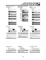
Отзывы: