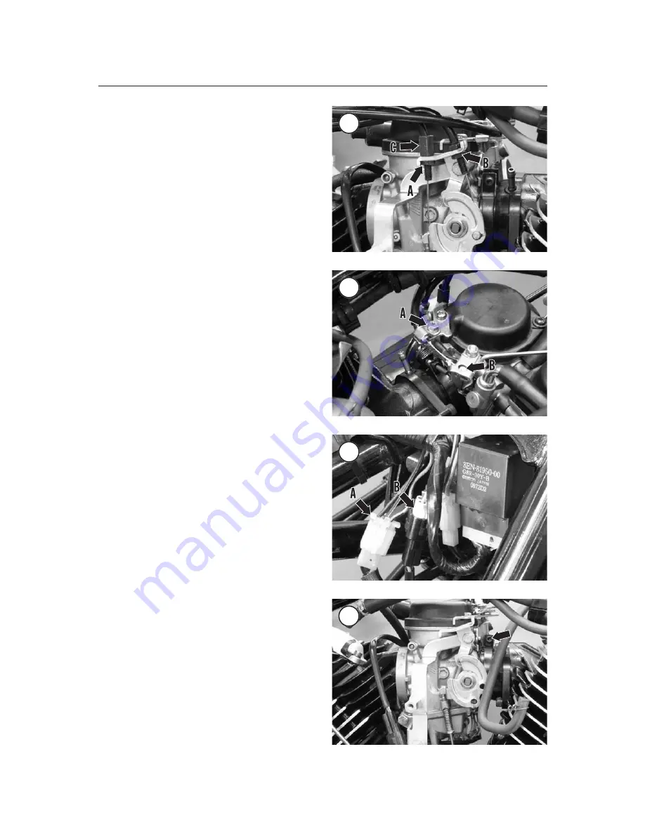
from the carburetor bracket and disconnect the ca-
ble ends from the throttle wheel. If necessary, turn
the pull cable adjuster (C,
Figure 26
) to create addi-
tional slack.
12. Loosen the cable clamp screw (A,
Figure 27
)
and disconnect the choke cable end (B) from the
choke linkage.
13. Move the throttle and choke cables out of the
way.
NOTE
Do not remove the throttle position
sensor from the carburetor body. Re
fer to
Throttle Position Senso
r in this
chapter for TPS inspection and ad
justment procedures.
14. Disconnect the three-pin carburetor heater con-
nector (A,
Figure 28
) and the triangular, three-pin
throttle position sensor (B) from their harness mates.
15. Loosen the clamp screw (
Figure 29
) that se-
cures each carburetor to its intake manifold.
16. Pull the carburetors from the intake manifolds
and remove the assembly from the left side of the
motorcycle.
17. On California models, remove the heat shield
(
Figure 30
).
18. While the carburetor assembly is removed, exam-
ine the intake manifold on each cylinder head. Look
for cracks or other damage that would allow unfiltered
air into the engine. Replace any damaged part.
19. Stuff clean shops rag into each intake manifold
to keep foreign matter out of the cylinder heads.
20. Install the carburetor assembly by reversing
these removal steps. Note the following:
CAUTION
The carburetors form an airtight seal
with the manifolds. Air leaks can
cause engine damage due to a lean
air/fuel mixture or dirt entering with
the incoming air.
a. On California models, hook the heat shield
(
Figure 30
) over each intake.
b. Lubricate each intake manifold with a little
soap to ease installation.
c. Install the carburetor assembly from the left
side and fully seat each carburetor in its intake
manifold. A solid bottoming will be felt when
a carburetor is correctly installed. Tighten each
carburetor clamp (
Figure 29
) securely.
212
CHAPTER EIGHT
26
27
28
29


