NOTE
In the next step, install the second
circlip with the gap away from the cut
out in the piston.
8. Install the second piston pin circlip (
Figure 118
)
into the groove in the piston. Make sure the circlip’s
end gap does
not
align with the notch in the piston
(
Figure 120
). Also, make sure both piston pin
circlips are seated in their grooves in the piston.
9. Check the installation by rocking the piston back
and forth around the pin axis and from side to side
along the axis. It should rotate freely back and forth,
but not from side to side.
10. If necessary, install the piston rings as de-
scribed in this chapter.
12. Install the cylinder and cylinder head as de-
scribed in this chapter.
Piston Inspection
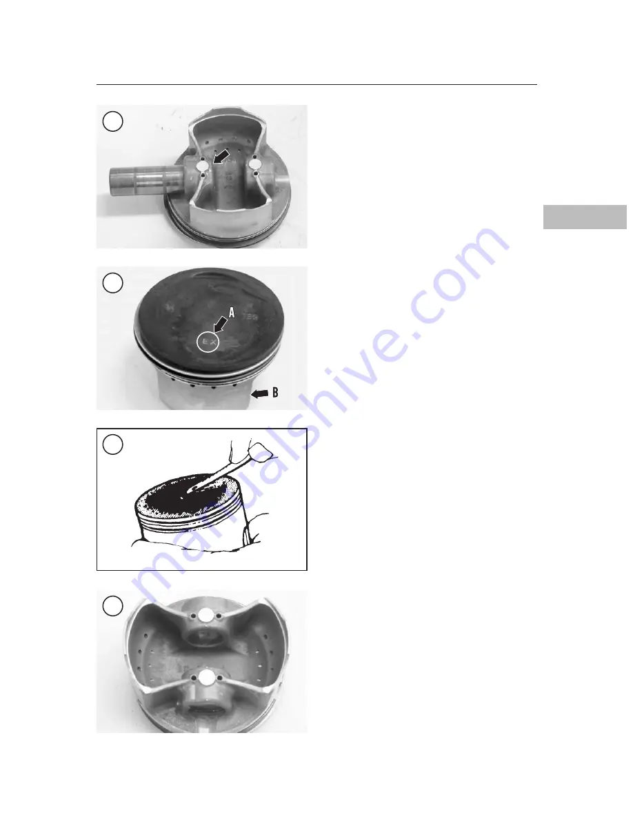
1. Carefully clean the carbon from the piston
crown (
Figure 123
) with a chemical remover or
with a soft scraper. Re-mark the piston as soon as it
is cleaned. Do not remove or damage the carbon
ring around the circumference of the piston above
the top ring. If the piston, rings and cylinder are
dimensionally correct and can be reused, removal
of the carbon ring from the top of the piston or re-
moval of the carbon ridge from the top of the cylin-
der block wall will promote excessive oil
consumption in this cylinder.
CAUTION
Do not use a wire brush on the piston
skirts.
2. After cleaning the piston, examine the crown. It
should show no signs of wear or damage.
3. Examine each ring groove for burrs, dented
edges and wide wear. Pay particular attention to the
top compression ring groove. It usually wears more
than the other grooves. Since the oil rings are con-
stantly bathed in oil, these rings and grooves wear
little compared to compression rings and their
grooves. If the oil ring groove shows signs of wear,
or if the oil ring assembly is tight and difficult to re-
move, the piston skirt may have collapsed. If so,
replace the piston.
4. Check the oil control holes (
Figure 124
) in the
piston for carbon or oil sludge build-up. If neces-
ENGINE TOP END
125
4
121
122
123
124


