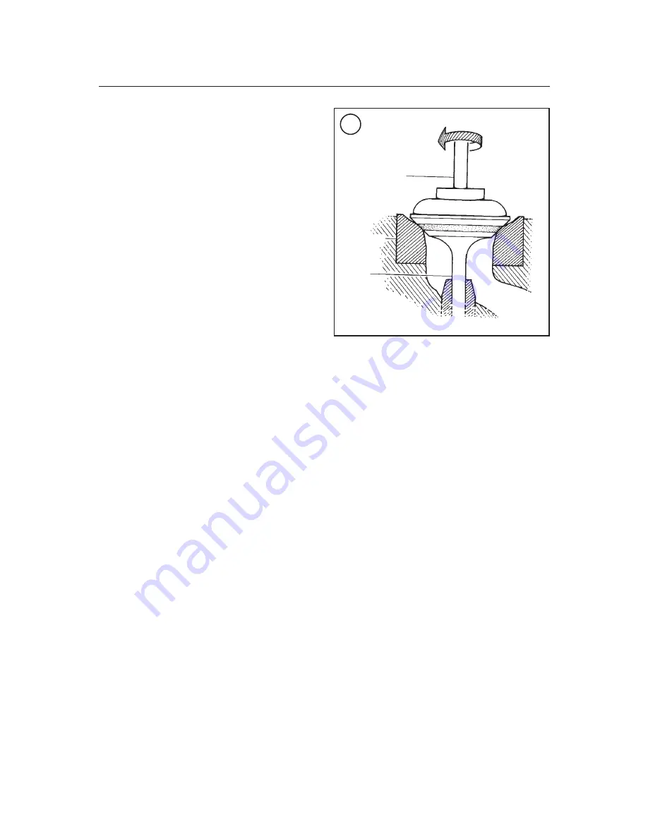
inder head, the valve seat should be tested. Check
the seat by performing the leakage test described in
the
Cylinder Head
section earlier in this chapter. If
fluid leaks past any of the seats, disassemble that
valve assembly and repeat the lapping procedure
until there are no leaks.
7. After the cylinder head and valve components
are cleaned in detergent and hot water, apply a light
coat of engine oil to all bare metal surfaces to pre-
vent rust.
CYLINDER
Refer to
Figure 108
.
Removal
1. Remove the cylinder head and head gasket as de-
scribed in this chapter.
2. If the front cam chain guide is still installed, re-
move it from the cylinder.
3. Remove the cylinder bolts (A and B,
Figure 109
)
from the cam chain side of the cylinder. One bolt sits
in a recess (B,
Figure 109
) in the top of the cylinder.
4. Loosen the cylinder by tapping around the per-
imeter with a rubber or plastic mallet.
5. Pull the cylinder straight up, and lift it off the
pistons and cylinder studs.
NOTE
Be sure to keep the cam chain wired
up to prevent it from falling into the
crankcase.
6. Remove the two dowels (A,
Figure 110
) from
the exhaust side of the cylinder.
7. Remove and discard the base gasket (B,
Figure
110
).
8. Stuff clean shop rags into the crankcase opening
to prevent objects from falling into the crankcase.
Also place a length of hose (
Figure 111
) over each
crankcase stud the piston leans against so the rings
will not be marred if the piston is accidentally struck.
9. Inspect the cylinder as described in this section.
Installation
1. Make sure the top and bottom cylinder surfaces
are clean of all gasket residue.
2. Install the two dowels (A,
Figure 110
) and new
base gasket (B).
3. Lubricate the cylinder and piston liberally with
engine oil prior to installation.
4. Rotate the crankshaft so the piston is at top dead
center.
5. Carefully install the cylinder onto the crankcase
studs. Make sure the cam chain and rear cam chain
guide pass through the cam chain tunnel in the cyl-
inder.
6. Slowly lower the cylinder until the piston rings
are within the cylinder sleeve (
Figure 112
). Com-
press each ring as it enters the cylinder with your
fingers or with a piston ring compressor. Take the
time to carefully compress each ring individually if
necessary.
7. Run the cam chain and safety wire up through
the cam chain tunnel in the cylinder, and secure the
safety wire to the outside of the engine.
8. Carefully lower the cylinder all the way down
onto the crankcase and install the cylinder bolts
(
Figure 113
) into the cam chain side of the cylinder.
Finger-tighten the bolts at this time. They will be
torqued after the cylinder head hardware has been
torqued.
9. Install the cylinder head and torque the cylinder
head hardware to specification as described in this
chapter.
11. Torque the cylinder bolts (A and B,
Figure
109
) to 10 N•m (89 in.-lb.). One of the bolts sits in a
recess (B,
Figure 109
) in the cylinder block.
120
CHAPTER FOUR
107
Valve lapper
Valve seat
Valve


