cam chain drive assembly is installed
in the correct cylinder.
2. Preload the cam chain drive assembly as follows:
a. Cut a 6 × 15 mm pin from the shoulder
(non-threaded portion) of a 6-mm bolt.
b. Use a screwdriver or similar tool to pry the
drive teeth on the gear until one set of teeth
aligns with the other.
c. Insert the 6-mm pin (
Figure 58
) into the
aligned hole to lock the gear.
3. Position the timing gear so the side with the
3
stamp faces the outboard side of the engine, and seat
the cam chain (A,
Figure 59
) on the sprocket of the
cam chain drive assembly (B).
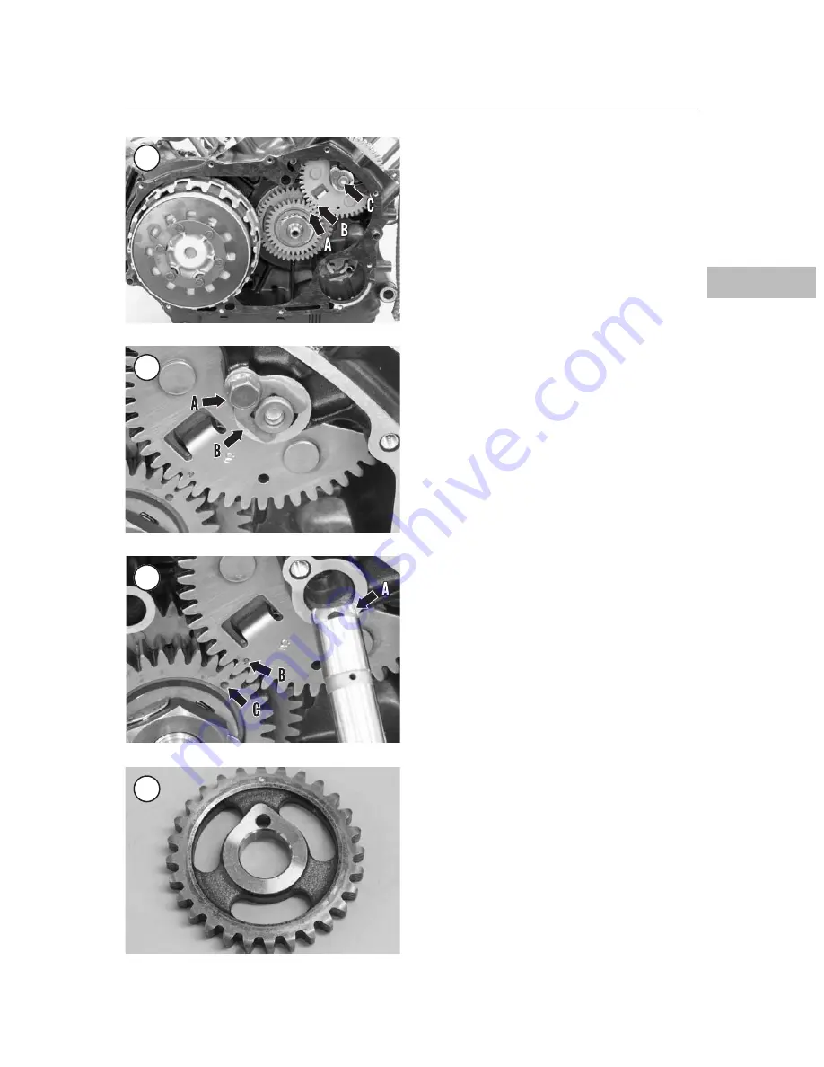
4. Lower the cam chain drive assembly into the
cam chain tunnel until the teeth of the drive assem-
bly gear engage the teeth of the timing gear. Make
sure the timing mark on the cam chain drive assem-
bly (B,
Figure 69
) aligns with the mark on the front
cylinder timing gear (C).
5. Install the shaft so the oil cutout faces up (A,
Figure 69
).
6. Slide the retainer (B,
Figure 68
) over the end of
the shaft so the retainer fingers seat in the cutout in
the shaft.
7. Install the retainer bolt (A,
Figure 68
). Apply a
medium-strength threadlocking compound to the
bolt threads, and torque the cam chain drive assem-
bly retainer bolt to 10 N•m (89 in.-lb.).
8. Remove the 6-mm pin (
Figure 58
) from the cam
chain drive assembly.
Inspection
NOTE
If a cam chain or cam chain drive as
sembly must be replaced, replace the
chain, drive assembly and the cam
sprocket as a set.
1. Inspect the cam chain (A,
Figure 59
) for wear,
stretching or link damage.
2. Inspect the teeth of the cam sprocket (
Figure 70
)
and the sprocket on the cam chain drive assembly
(B,
Figure 59
) for worn or broken teeth.
3. Inspect the sliding surface (
Figure 71
) of each
chain guide.
4. Inspect the pivot point on the rear chain guide (the
bolted guide). Make sure the pivot moves freely. If
necessary, replace the rear chain guide as follows:
ENGINE TOP END
109
4
67
68
69
70


