3. Inspect the grooves carefully for burrs, nicks or
broken and cracked lands. Recondition or replace
the piston if necessary.
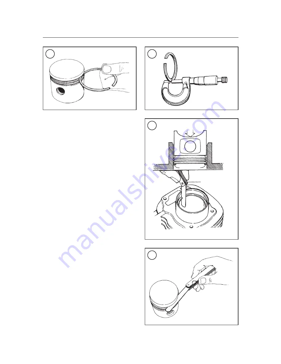
4. Roll each ring around its piston groove as shown
in
Figure 131
to check for binding. Minor binding
may be cleaned up with a fine-cut file.
5. Measure the thickness of each ring with a mi-
crometer (
Figure 132
). If the thickness is less than
the value specified in
Table 2
, replace the ring(s).
NOTE
When checking the oil control ring as
sembly, just measure the end gap of
each ring rail. The end gap of the ex
pander spacer cannot be measured. If
either ring rail has excessive end gap,
replace the entire oil ring assembly.
6. Place each ring, one at a time, into the cylinder,
and push the ring to a point 40 mm (1.57 in.) below
the top of the cylinder. Push the ring with the crown
of the piston to ensure the ring is square in the cylin-
der bore. Measure the ring end gap with a flat feeler
gauge (
Figure 133
). If the gap is out of specifica-
tion (
Table 2
), replace the rings.
7. Install the piston rings as described below and
measure the side clearance of each ring in its groove
with a flat feeler gauge (
Figure 134
). If the clear-
ance is greater than specified, replace the piston and
rings as a set.
8. When installing new rings, measure their end
gaps as described in Step 5, and compare the mea-
surements to the dimensions given in
Table 2
. If the
end gap is greater than specified, return the rings for
another set(s). If the end gap is smaller than speci-
fied, secure a small file in a vise, grip the ring with
your fingers, and enlarge the gap (
Figure 135
).
128
CHAPTER FOUR
131
132
133
Feeler gauge
Piston ring
134


