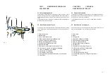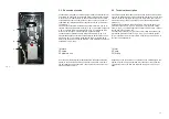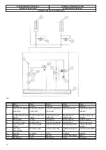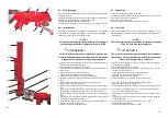
Fig. 4
3.3 Descrizione tecnica
Il sollevatore e' progettato e costruito per permettere il sollevamento di
autovetture ed il riscontro di carrozzeria e telaio (tramite apparecchiatu-
re esterne) per la raddrizzatura. La sua struttura consente una veloce
salita delle autovetture, senza l’utilizzo di pedane e la sua struttura ri-
sulta ideale per l‘affiancamento ad attrezzature esterne (come banchi
con dime etc.)
Fisicamente il sollevatore è costituito da un telaio inferiore, che ne co-
stituisce il basamento da fissare a terra (2, fig. 3), da un telaio superiore
(l, fig. 3) e da due bracci di sollevamento (3, fig. 3), collegati tra loro a
forbice e che collegano il telaio superiore a quello inferiore.
Il sollevamento è realizzato da due cilindri oleodinamici (4, fig. 3) co-
mandati dalla apposita centrale situata all’interno della centralina di co-
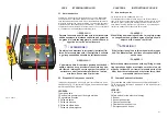
mando (12, fig. 3). La centrale oleodinamica (fig. 4) è formata da un
motore che comanda una pompa idraulica. L’olio è situato nell’apposito
serbatoio di cui è munita.
1 Motore
2 Pompa
3 Serbatoio olio
A seconda dei comandi premuti dall’utilizzatore sull’apposita tastiera
mobile, la centrale oleodinamica pompa olio in pressione o richiama
olio dai cilindri posti sul sollevatore, i quali permettono la salita o la di-
scesa del telaio superiore
3.3 Technical description
THe lift is designed and made to lift cars and so that bodywork and fra-
mes can be straightened by means of external equipment. Thanks to its
structure it lifts cars quickly without the use of platforms and is ideal if
external equipment need to be used next to it (like benches with tem-
plates, etc
.).
Physically the lift consists of a bottom frame, which is the base to be
anchored to the floor (2, Fig. 3), a top frame (l, Fig. 3) and two lifting
arms (3, Fig. 3), connected together as scissors which, in turn, connect
the top frame to the bottom one.
Two hydraulic cylinders (4, Fig. 3) are used for lifting controlled by the
unit located inside the control unit (12, Fig. 3). The hydraulic system
(Fig. 4) consists of a motor that controls a hydraulic pump. The oil is in
the tank it is equipped with
.
1 Motor
2 Pump
3 Oil tank
Depending on the controls the user presses on the mobile keypad, the
hydraulic system pumps pressurised oil or takes the oil back from the
cylinders that are on the lift which allow the top frame to move up or
down.
17
1
2
3
Содержание RPK25/B
Страница 2: ......
Страница 22: ...SCHEMA ELETTRICO ELECTRIC WIRING SCHEME SCH MA LECTRIQUE ELEKTRISCHER ANSCHLUSSPLAN ESQUEMA EL CTRICO Fig 7...
Страница 53: ......
Страница 58: ...QUADRO ELETTRICO TRIFASE 3PH CONTROL PANEL SCHALTTAFEL DREHSTROM 3PH COFFRET LECTRIQUE 3PH CUADRO ELECTRICO 3PH...
Страница 59: ...CENTRALINA OLEODINAMICA OLEODYNAMIC CONTROL UNIT HYDRAULIKEINHEIT CENTRALE HYDRAULIQUE CENTRALITA HIDRAULICA...


