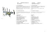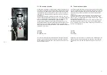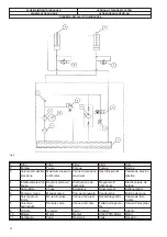
Fig.2
2.2 Utilizzatore appropriato
La semplicità di funzionamento del sollevatore non richiede qualifica
supplementare rispetto a quanto riportato nel capitolo 1, paragrafo 1.2.
La lettura del presente manuale si ritiene sufficiente a garantire una
preparazione che assicuri di poter correttamente operare con il solleva-
tore stesso. Si dovrà curare in particolare gli aspetti inerenti la Sicurez-
za per l’Uomo e per 1’Ambiente. Gli interventi di regolazione o manu-
tenzione dovranno essere eseguiti da operatori preventivamente qualifi-
cati secondo quanto prescritto al capitolo 1, paragrafo 1.2.
2.3 Fornitura
Di seguito vengono elencate tutte le parti di cui si compone il sollevatore e
che vengono fornite al Cliente:
·
sollevatore;
·
centralina di comando comprensiva di pulsantiera mobile;
·
braccio di tiro, composto dalle seguenti parti:
·
staffa di supporto orizzontate con piastra per il fissaggio;
·
braccio verticale;
·
n° 3 ruote rimovibili, per la movimentazione a terra del braccio completo;
·
catena di tiro con morsetto per fissaggio al braccio, gancio e cavo di sicu-
rezza;
·
n° 1 cilindro ad azionamento pneumatico con forcella.
·
n° 4 staffe di supporto per sostegno autovettura;
·
n° 4 piattelli gommati
·
n° 4 morse per aggancio vettura;
·
n°4 cavalletti
·
n° 4 tasselli a espansione per il fissaggio a terra del basamento.
Oltre alle parti suddette, a richiesta del cliente, può essere fornito anche il se-
guente accessorio (optional):
·
pompa pneumatica (fig. 2) per 1’azionamento del braccio di tiro.
La trattazione di tutte le parti sopra elencate ed il loro funzionamento è
riportata nel capitolo 3 del presente manuale.
2.2 Appropriate user
The simplicity of use of the lift requires no additional qualification to
what is specified in Chapter 1, paragraph 1.2. Reading this manual is
deemed sufficient to guarantee a preparation that ensures the lift can
be operated correctly. The safety aspects must be observed in particu-
lar for both man and environment. All adjustments and maintenance
work must be carried out by operators who are already qualified accor-
ding to what is prescribed in Chapter 1, paragraph 1.2.
2.3 Supply
Below is a list of all the parts that make up the lift and which are sup-
plied to the customer:
·
lift;
·
control unit including the mobile push button panel;
·
pulling arm consisting of the following parts:
·
horizontal support bracket with fixing plate;
·
vertical arm;
·
no.3 removable wheels for moving the arm assembly along the ground;
·
pulling chain with clamp for fixing to the arm, hook and safety cable;
·
no. 1 pneumatically operated cylinder with fork.
·
no. 4 brackets to support the vehicle;
·
no. 4 rubberised plates
·
no. 4 vices for gripping the vehicle;
·
no. 4 stands
·
no. 4 expansion bolts for anchoring the base to the floor
.
Besides the aforementioned parts, the following accessory may also be
requested by the customer (optional feature
):
·
pneumatic pump (Fig. 2) for operating the pulling arm.
All the aforementioned parts and their operation are explained in Chap-
ter 3 of this manual.
9
Содержание RPK25/B
Страница 2: ......
Страница 22: ...SCHEMA ELETTRICO ELECTRIC WIRING SCHEME SCH MA LECTRIQUE ELEKTRISCHER ANSCHLUSSPLAN ESQUEMA EL CTRICO Fig 7...
Страница 53: ......
Страница 58: ...QUADRO ELETTRICO TRIFASE 3PH CONTROL PANEL SCHALTTAFEL DREHSTROM 3PH COFFRET LECTRIQUE 3PH CUADRO ELECTRICO 3PH...
Страница 59: ...CENTRALINA OLEODINAMICA OLEODYNAMIC CONTROL UNIT HYDRAULIKEINHEIT CENTRALE HYDRAULIQUE CENTRALITA HIDRAULICA...


