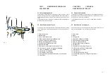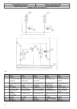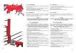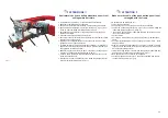
Fig.9
4.3 Disimballaggio
La rimozione dell’imballo si esegue secondo la sequenza di operazioni
di seguito riportate:
togliere le reggette che fissano la cassa degli accessori al sollevatore;
rimuovere la cassa utilizzando un sollevatore a pale;
rimuovere il coperchio superiora della cassa;
aprire la cassa più piccola e rimuovere. tutte le parti in essa contenute.
4.4 Installazione
Posizionato il sollevatore nella postazione di istallazione, o in prossimi -
tà della stessa e rimosso l’imballaggio, si inizi l’opera di rimontaggio
eseguendo la procedura di seguito de-scritta:
! NOTA !
La procedura di seguito riportata illustra il rimontaggio
completo del sollevatore, compreso il braccio di tiro.
I
! ATTENZIONE !!
La scelta della postazione di installazione non può pre-
scindere dalla planarità del pavimento e dalle dimensioni
di ingombro del sollevatore, indicate nel capitolo 2.
·
Fissate a terra il sollevatore, tramite i quattro fori situati sul basamento ed
utilizzando i tassellid espansione forniti.
·
Montare il braccio di tiro agendo come segue:
·
inserire sulla traversa orizzontale (1, fig. 9) le ruote (2) e fissarle con le ap-
posite viti (3);
·
inserire la traversa orizzontale all’attacco (4);
·
inserire il perno (5) e fissalo con un anello seeger;
·
inserire il perno (6) per bloccare la rotazione del braccio;
·
appoggiare il braccio verticale (7) ulla apposita sede. del braccio orizzon-
tale;
·
inserire la ghiera (8) e fissare il tutto con i nove bulloni M16 (9);
·
avvitare la forcella (10) sul cilindro (11);
·
fissare il cilindro all’apposita staffa, tramite il perno (12) e la relativa copi-
glia;
·
posizionare la rotella di scorrimento (13) della catena., nella posizio-
ne desiderata, fissandola con il perno (14) e la relativa copiglia;
·
fissare la catena (15) alla staffa (16) e posizionarla come mostrato in
figura;
·
inserire tutto il braccio sul telaio superiore del sollevatore, quando questo
è in appoggio sulla staffa di sicurezza;
·
tirare indietro le due leve (17), bloccando il braccio sul sollevatore;
·
inserire il cuneo (18) di sicurezza;
·
collegare al cilindro la pompa esterna.
4.3 Unpacking
To remove the packaging follow these steps:
first take the straps off that are fixing the crate of accessories to the lift;
remove the crate using a forklift truck;
remove the top lid of the crate;
open the smallest crate and take all the parts out of it.
4.4 Installing
Once the lift has been placed where it is going to be installed, or near it,
and the packaging removed, start assembly following the procedure de-
scribed below
:
! NOTE !
The following procedure illustrates completely assembly
of the lift, including the pulling arm
.
I
!! ATTENTION !!
The choice of installation place must take into considera-
tion the floor, which must be even, and the overall dimen-
sions of the lift, specified in Chapter 2.
·
Anchor the lift to the floor, using the four holes on the base and the
expansion bolts supplied
.
·
Assemble the pulling arm as follows:
·
insert the wheels (2) on the horizontal cross element (1, Fig. 9) and
fix them with the screws (3);
·
fit the horizontal cross element on the coupling (4);
·
insert the pin (5) and fix it with a snap ring;
·
insert the pin (6) to lock arm rotation;
·
fit the vertical arm (7) in its place on the horizontal arm;
·
insert the ring nut (8) and fix it all with nine M16 bolts (9);
·
tighten the fork (10) on the cylinder (11);
·
fix the cylinder on the bracket using the pin (12) and relative split pin;
·
position the chain sliding wheel (13) in the position wanted, fixing it
with the pin (14) and relative split pin;
·
fix the chain (15) to the bracket (16) and position it as shown in the fi-
gure;
·
fit the whole arm on the top frameof the lift when it is resting against
the safety bracket;
·
pull the two levers (17) back, locking the arm on the lift;
·
insert the safety wedge (18);
·
connect the external pump to the cylinder
25
17
18
3
6
5
4
2
10
1
8
9
11
7
16
12
15
13
14
Содержание RPK25/B
Страница 2: ......
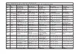
Страница 22: ...SCHEMA ELETTRICO ELECTRIC WIRING SCHEME SCH MA LECTRIQUE ELEKTRISCHER ANSCHLUSSPLAN ESQUEMA EL CTRICO Fig 7...
Страница 53: ......
Страница 58: ...QUADRO ELETTRICO TRIFASE 3PH CONTROL PANEL SCHALTTAFEL DREHSTROM 3PH COFFRET LECTRIQUE 3PH CUADRO ELECTRICO 3PH...
Страница 59: ...CENTRALINA OLEODINAMICA OLEODYNAMIC CONTROL UNIT HYDRAULIKEINHEIT CENTRALE HYDRAULIQUE CENTRALITA HIDRAULICA...


