·
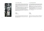
Collegare il tubo di alimentazione aria dall’esterno al raccordo rapido,
posto sulla centralina.
·
Collegare il tubo di collegamento dell‘aria in uscita dalla centralina, al
raccordo posto sul sollevatore.
·
Collegare i tubi dell’impianto oleodinamico della centralina, ai raccor-
di rapidi del sollevatore,
·
Collegare l’alimentazione elettrica (400 V - 50 Hz trifase) alla centrali-
na tramite l’apposita presa ad innesto.
! NOTA !
Per quanto riguarda il montaggio e l’utilizzo delle
staffe di supporto autovettura e delle altre parti da inseri-
re sulle stesse, si rimanda alle procedure di utilizzo, de-
scritte nel capitolo 5,
4.5 Condizioni ambientali previste per il funzionamento
Il sollevatore è concepito per lavorare all’interno delle carrozzerie per
autovetture, pertanto i parametri arnbientali presi a riferimento sono i
seguenti
·
temperatura compresa tra +5°C ÷ 40°C
·
umidità compresa tra 30% ÷ 95% (senza condensa)
L‘ambiente in cui il sollevatore dovrà operare deve inoltre possedere le
seguenti caratteristiche:
·
la struttura di copertura dell’ambiente deve essere sufficientemente
alta, a tal fine si precisa che:
·
Altezza soffitto > Altezza v Altezza sollevatore alla massima
estensione;
·
la pavimentazione deve essere priva di pendenza, dossi o asperità
che potrebbero comportare pericoli in fase di movimentazione a terra
del sollevatore con carico.
Non è previsto l’uso del sollevatore in ambienti aventi caratteristiche di-
verse da quanto sud-detto, o speciali (come es. ambienti autodeflagran-
di.; ecc.).
I
!! ATTENZIONE !!
L’uso del sollevatore in ambienti o situ azioni non
previste solleverà il Costruttore dalle responsabilità
derivanti da tale utilizzo.
·
Connect the external air supply pipe to the quick coupling on the unit
·
Connect the air supply pipe coming from the unit to the fitting on the
lift
·
Connect the pipes of the hydraulic system unit to the lift’s quick cou-
plings
·
Connect the electricity supply (400 V - 50 Hz three-phase) to the unit
by means of the plug-in socket
.
! NOTE !
As far as concerns assembly and use of the car sup-
porting brackets and the other parts to be fitted on
them, please refer to procedures for using, described
in Chapter 5,
4.5 Environmental conditions for working
The lift is conceived for working inside car body workshops hence the
environmental parameters taken as reference are the following
·
temperature ranging b5°C ÷ 40°C
·
humidity ranging between 30% ÷ 95% (without condensation
)
The premises on which the lift has to work must also have the following cha-
racteristics:
·
the structure of the roof of the premises must be sufficiently high, and
more specifically:
·
Ceiling height > Car Lift height when extended to its maxi-
mum;
·
the floor must be completely flat, with no sloping, humps or roughness that
could be a source of danger when moving the lift plus load along the gro-
und.
Use of the lift is not contemplated in environments with characteristics
different from those specified above, or special characteristics (e.g. on
premises where there is the risk of explosion, etc.).
I
!! ATTENTION !!
If the lift is used on premises or in situations that are
not foreseen, the Manufacturer is relieved from all lia-
bilities deriving from such use
27
Содержание RPK25/B
Страница 2: ......
Страница 22: ...SCHEMA ELETTRICO ELECTRIC WIRING SCHEME SCH MA LECTRIQUE ELEKTRISCHER ANSCHLUSSPLAN ESQUEMA EL CTRICO Fig 7...
Страница 53: ......
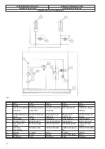
Страница 58: ...QUADRO ELETTRICO TRIFASE 3PH CONTROL PANEL SCHALTTAFEL DREHSTROM 3PH COFFRET LECTRIQUE 3PH CUADRO ELECTRICO 3PH...
Страница 59: ...CENTRALINA OLEODINAMICA OLEODYNAMIC CONTROL UNIT HYDRAULIKEINHEIT CENTRALE HYDRAULIQUE CENTRALITA HIDRAULICA...


