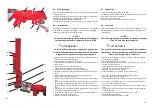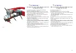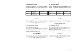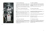
Fig.11
I
!! ATTENZIONE !!
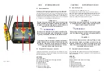
Assicurarsi che il cavo della pulsantiera non si trovi
nell’ingombro del telaio.
e. Operazioni da compiere per il caricamento dell’autovettura.
·
Abbassare completamente il sollevatore.
·
Posizionare l’autovettura sullo stesso, centrandola il più possibile
.
·
Agganciare alla piattaforma le 4 staffe di sostegno (1, fig.11), inse-
rendo su ciascuna staffa i piattelli gommati (4 fig.11)
·
dare attenzione a posizionare i supporti gommati nei giusti punti
scocca della vettura
·
Procedere al sollevamento dell`autoveicolo
·
Per normali lavori di carrozzeria é sufficiente il posizionamento della
vettura come sopra descritto.
·
Mentre per lavori straordinari dove sia necessario l’uso del “TIRO”
procedere come di seguito descritto
·
A vettura sollevata, come sopra descritto, utilizzare i “4 cavalletti”, e
dopo averli correttamente posizionati sotto le 4 ruote discendere ed
appoggiare la vettura sugli stessi.
·
Abbassare il ponte di ulteriori 15-20cm e sostituire i 4 supporti gom-
mati con i corrispondenti supporti-morsa (3, fig.11).
·
A questo punto procedere al posizionamento delle morse sotto car-
rozzeria dell’autoveicolo.
·
Risollevare la vettura ed assicurare le 4 staffe di sostegno tramite i
piatti ed i bulloni di bloccaggio (2, fig.11).
I
!! ATTENTION !!
Make sure the cable of the push button panel is not
entangled with the frame.
e. Operations to do to load the car
.
·
Lower the lift right down.
·
Position the car on it, centring it as accurately as possible.
·
Fasten the 4 supporting brackets (1, Fig.11) to the platform, fitting the
rubberised plates on each one (4, Fig.11)
·
take care in positioning the rubberised supports correctly on the po-
ints of the car bodywork
·
Lift the vehicle
·
For ordinary work on the body simply position the car as described
above.
·
For other extraordinary work it is necessary to use the “PULL”, proce-
eding as follows
·
With the car raised as described above, use the “4 stands” and after
they have been positioned correctly under the 4 wheels, lower the ve-
hicle until it is resting on them.
·
Lower the bridge another 15-20cm and change the 4 rubberised sup-
ports with the corresponding vice-supports (3, Fig.11).
·
Now position the vices under the car bodywork
.
·
Lift the car again and secure the 4 supporting brackets with the pla-
tes and fastening bolts (2, Fig.11)
35
2
1
4
3
Содержание RPK25/B
Страница 2: ......
Страница 22: ...SCHEMA ELETTRICO ELECTRIC WIRING SCHEME SCH MA LECTRIQUE ELEKTRISCHER ANSCHLUSSPLAN ESQUEMA EL CTRICO Fig 7...
Страница 53: ......
Страница 58: ...QUADRO ELETTRICO TRIFASE 3PH CONTROL PANEL SCHALTTAFEL DREHSTROM 3PH COFFRET LECTRIQUE 3PH CUADRO ELECTRICO 3PH...
Страница 59: ...CENTRALINA OLEODINAMICA OLEODYNAMIC CONTROL UNIT HYDRAULIKEINHEIT CENTRALE HYDRAULIQUE CENTRALITA HIDRAULICA...

