background image

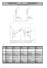
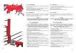
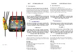
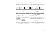
Fig.10 Abb.10

CAP.5

ISTRUZIONI PER L

USO

5.1 Note introduttive

Il sollevatore , richiede per la propria utilizzazione, un unico OPERATORE.
.Le operazioni che l‘operatore è chiamato a svolgere sul sollevatore,
sono estremamente semplici, dato il tipo di funzionamento del solleva-
tore stesso. Durante tutto il tempo di utilizzo, cioè durante le operazioni
di sollevamento e abbassamento delle autovetture, l’ utilizzatore deve
sempre stazionare a distanza di sicurezza (almeno 1,5 m) dal sollevato-
re, comandando i movimenti dalla pulsantiera mobile.

!! PERICOLO !!!

Durante l‘esecuzione delle manovre di sollevamento

e abbassamento, la distanza suddetta può garantire

un grado di sicurezza maggiore in caso di caduta di

oggetti o del carico dal sollevatore.

I

! ATTENZIONE !!

Qualora siano disattese le istruzioni riportate all’in-

terno del presente manuale, il Costruttore declinerà

ogni responsabilità derivante da tali inosservanze.

!!! PERICOLO !!!

L‘operatore prima di compiere qualunque attività di

salita, o discesa deve accertarsi che esista uno spa-

zio libero di almeno 50 cm tra ogni parte mobile del

sollevatore, o dell‘autovettura sollevata e le altre

strutture, fisse o mobili, più vicine.

5.2 Dispositivi di comando e controllo

I

dispositivi di comando e controllo posti sul sollevatore, sono

illustrati nella fig. 10, riportata di seguito e descritti nella legen-

da relativa alla figura stessa.

LEGENDA

1.Lampada spia.
2.Sezionatore generale per l’energia elettrica.
3.Segnalatore acustico
4, Pulsante salita
5. Pulsante discesa
6. Pulsante ultimo tratto
7. Pulsante d'emmergenza

CHAPTER 5

INSTRUCTIONS FOR USE

5.1 Introductory notes

The lift requires just one OPERATOR to work it.
The operations the operator is called to do on the lift are extremely
easy, given the type of operation of the lift itself. All the time the lift is in
use, that is, when it is lifting and lowering vehicles, the user must al-
ways stand at a safety distance from it (at least 1.5 m), controlling mo-
vements by means of the mobile push button panel.

!!! DANGER !!!

When lifting and lowering vehicles, this safety distan-

ce can guarantee a greater degree of safety should

objects or the load on the lift fall

.

I

ATTENTION !!

If the instructions given in this manual are disregar-
ded, The Manufacturer declines all responsibility in

such a case

.

!!! DANGER !!!

Before the operator proceeds with any lifting or lowe-

ring operations he/she must make sure there is a cle-

arance of at least 50 cm from all movable parts of the

lift or from the raised car and other structures, fixed

or movable, that are closest

.

5.2 Command and control devices

The command and control devices on the lift are illustrated in

Fig.10 and shown below and described in the legend pertai-

ning to the figure.

LEGEND

1.Pilot light.
2.Main switch for the electrical energy.
3. Buzzer
4. Ascent push button
5. Descent push button
6. Final descent push button
7. Emergency push button

31

2

1

3

7

4
5

6

4

5

6

Содержание RPK25/B

Страница 1: ...E Sollevatore elettroidraulico a forbice Electroydraulic scissor car lift Pont l vateur lectro hydraulique ciseaux Elektroidraulische Scherenheb hne Rampa tipo tijera electro hidraulico para autos RPK...

Страница 2: ......

Страница 3: ...Rampa tipo tijera electro hidraulico para autos Modello Model Mod le Modell Modelos RPK25 B COSTRUTTORE MANUFACTURER CONSTRUCTEUR HERSTELLER FABRICANTE WERTHER INTERNATIONAL S p A Via F BRUNELLESCHI...

Страница 4: ...CUREZZA 39 Cap 7 INTERVENTI DI MANUTENZIONE 43 Appendice A Informazioni 49 Appendice B Parti di ricambio 49 INDEX Chapter 1 INTRODUCTION 4 Chapter 2 GENERAL DESCRIPTION 8 Chapter 3 TECHNICAL DESCRIPTI...

Страница 5: ...EINE BESCHREIBUNG 8 Kap 3 TECHNISCHE BESCHREIBUNG 16 DER HEBEB HNE Kap 4 INSTALLATION DER HEBEB HNE 24 Kap 5 BENUTZUNGSANWEISUNGEN 32 Kap 6 SICHERHEITSBESTIMMUNGEN 40 Kap 7 WARTUNGSARBEITEN 44 Anhang...

Страница 6: ...ropee 2004 108 CE 2006 42 CE 2006 95 CE NORME TECNICHE Norme Europee EN 1493 2010 EN ISO 12100 1 2005 EN ISO 12100 2 2005 IMPIANTO ELETTRICO EN 60204 1 CHAPTER 1 INTRODUCTION IWARNING This manual has...

Страница 7: ...e Sicherheit des zu hebenden Fahrzeuges AUFBEWAHRUNG DES HANDBUCHES Das Handbuch stellt ein Teil der Hebeb hne dar und muss diese immer begleiten auch wenn sie verkauft wird Das Handbuch muss immer an...

Страница 8: ...l manuale troverete spesso le diciture operatore e manuten tore il cui significato il seguente OPERATORE persona addetta all uso del sollevatore MANUTENTORE persona addetta alla manutenzione ordinaria...

Страница 9: ...cksichtigt die auch dem Bediener oder dem Wartungsfachmann f r ein besseres Verstehen der Struktur und des Betriebs der Hebeb hne sowie f r einen besseren Gebrauch derselben n tzlich sein k nnen Zum V...

Страница 10: ...KAP 2 ALLGEMEINE BESCHREIBUNG 2 1Abmessungen der Hebeb hne Die Abmessungen der Hebeb hne werden auf der folgenden Abb 1 wiedergegeben HINWEIS Um die gesamte Hebeb hne herum muss ein Freira um von zum...

Страница 11: ...guente accessorio optional pompa pneumatica fig 2 per 1 azionamento del braccio di tiro La trattazione di tutte le parti sopra elencate ed il loro funzionamento riportata nel capitolo 3 del presente m...

Страница 12: ...ebeb hne Steuereinheit einschlie lich mobiler Bedieneinheit Zugarm bestehend aus den folgenden Bauteilen horizontaler Halterungsb gel mit Platte f r die Befestigung vertikaler Arm 3 abnehmbare R der f...

Страница 13: ...a 350 mm nDimensioni centralina di comando nlunghezza 650 mm nlarghezza 450mm naltezza 220 mm nPeso sollevatore con accessori 400 kg nPeso centralina di comando 50 kg 2 4 Identification of the various...

Страница 14: ...r Hebeb hne nMax Tragkraft 3 000 kg n ltank 7 l nMax Hydraulikdruck mit 2 500 kg Last 275 bar nHydraulikdruck beim Betrieb 210 bar nStromversorgung in Abh ngigkeit von der Version siehe Abschnitt 2 4...

Страница 15: ...interno del capitolo 6 PERICOLO Il Costruttore raccomanda 1 esecuzione delle singo le attivit da parte di un unico addetto affinch sia no evitate condizioni di reciproca esposizione a ri schi 2 6 Type...

Страница 16: ...in bereinstimmung mit den Bestimmungen der anwendbaren EU Richtlinien sowie der davon abgeleiteten Referen znormen konzipiert und realisiert Wir empfehlen den Bedienern unter Beachtung der vorgeschri...

Страница 17: ...ncio e morsetto di fissaggi 11 Cavo di sicurezza per catena 12 Centralina di comando 13 Pulsantiera di comando 14 Pompa pneumatica per braccio di tiro optional 15 Cavalletto CHAPTER 3 TECHNICAL DESCRI...

Страница 18: ...e Die Lage der Hauptbauteile aus denen die Hebeb hne besteht wird auf Abb 3 wiedergegeben einschlie lich der Zubeh rteile 1 oberer Rahmen 2 Unterbau 3 Hubarme 4 Hydraulikzylinder Hub 5 Fahrzeughalteru...

Страница 19: ...zzatore sull apposita tastiera mobile la centrale oleodinamica pompa olio in pressione o richiama olio dai cilindri posti sul sollevatore i quali permettono la salita o la di scesa del telaio superior...

Страница 20: ...Rahmen l Abb 3 und zwei Hubarmen 3 Abb 3 mit einer Scheren verbindung die den oberen Rahmen mit dem unteren verbinden Das Anheben erfolgt durch zwei Hydraulikzylinder 4 Abb 3 die von einer entsprechen...

Страница 21: ...SCHEMA ELETTRICO ELECTRIC WIRING SCHEME SCH MA LECTRIQUE ELEKTRISCHER ANSCHLUSSPLAN ESQUEMA EL CTRICO Fig 5 Fig 6 19...

Страница 22: ...SCHEMA ELETTRICO ELECTRIC WIRING SCHEME SCH MA LECTRIQUE ELEKTRISCHER ANSCHLUSSPLAN ESQUEMA EL CTRICO Fig 7...

Страница 23: ...AC BUZER 24VAC BUZER 24VAC BUZER 24VAC BUZER 24VAC SBS B6527 PULSANTE D 22 1XNO NERO F BLACK PUSH BUTTON D 22 1XNO POUSSOIR DOUBLE ERSCE DOPPLER KNOPF KONTAKTGEBER PULSADOR DOBLE CON CONTACTO SBD B652...

Страница 24: ...Descent solenoid valve lectrovanne de descente Magnetventil Absenkung Electrov lvula de bajada 5 Strozzatore Choke trangleur Drosselventil Estrangulador 6 Pompa a mano Manual pump Pompe manuwele Hand...

Страница 25: ...tiche temperatura compresa fra 25 C e 55 C per periodi lunghi e tra 25 C e 70 C per peri odi inferiori a 24 ore umidit relativa compresa fra 30 e 95 senza condensa Non sono previsti luoghi di immagazz...

Страница 26: ...ackt ist da kein Zubeh r f r die Bewegung vorge sehen ist Die Hydraulikeinheit muss mit einem Schaufellader gehoben werden w hrend sie f r die Bewegung am Boden mit entsprechenden R dern ausgestattet...

Страница 27: ...cio sul telaio superiore del sollevatore quando questo in appoggio sulla staffa di sicurezza tirare indietro le due leve 17 bloccando il braccio sul sollevatore inserire il cuneo 18 di sicurezza colle...

Страница 28: ...garms wie folgt vor Setzen Sie die R der 2 in den horizontalen Tr ger 1 Abb 9 und befe stigen Sie sie mit den entsprechenden Schrauben 3 setzen Sie den horizontalen Tr ger in den Anschluss 4 ein setze...

Страница 29: ...di ecc I ATTENZIONE L uso del sollevatore in ambienti o situ azioni non previste sollever il Costruttore dalle responsabilit derivanti da tale utilizzo Connect the external air supply pipe to the qui...

Страница 30: ...en konzi piert und daher wurden f r die Umgebungsparameter Temperaturen zwischen 5 C 40 C ber cksichtigt Relative Feuchte zwischen 30 95 ohne Kondensbildung Die Umgebung in der die Hebeb hne eingesetz...

Страница 31: ...modo da assicurarel interruzione automatica dell alimentazione in caso di guasto all isolamento del sollevatore stesso 4 6 Installation characteristics Installation of the lift must take into conside...

Страница 32: ...requenz es ist eine max Leistungsaufnahme von 3 kW das Erdungskabel muss einen Mindestquerschnitt von 2 5 mm aufweisen G750 230 400 V 10 dreiphasig Erde und 50 Hz 2 Frequenz es ist eine max Leistungsa...

Страница 33: ...iva alla figura stessa LEGENDA 1 Lampada spia 2 Sezionatore generale per l energia elettrica 3 Segnalatore acustico 4 Pulsante salita 5 Pulsante discesa 6 Pulsante ultimo tratto 7 Pulsante d emmergenz...

Страница 34: ...heit garantieren I ACHTUNG Falls die im vorliegenden Handbuch enthaltenen Anwei sungen nicht befolgt werden bernimmt der Hersteller keinerlei Haftung f r die eventuellen daraus folgenden Sch den GEFAH...

Страница 35: ...leto del sollevatore e Premere il pulsante discesa 5 fino alla chiusura completa delle piattaforma utilizzando nell ultimo tratto contemporaneamente il relativo pulsante 6 5 3 Operating procedures A d...

Страница 36: ...sition O c Heben Stellen sie nach dem Einschalten sicher dass das Anheben der He beb hne nicht behindert wird Dr cken Sie die Taste 4 Abb 10 und halten Sie sie gedr ckt bis die gew nschte Position err...

Страница 37: ...o procedere al posizionamento delle morse sotto car rozzeria dell autoveicolo Risollevare la vettura ed assicurare le 4 staffe di sostegno tramite i piatti ed i bulloni di bloccaggio 2 fig 11 I ATTENT...

Страница 38: ...inden Heben Sie das Fahrzeug an F r normale Karosseriearbeiten ist es ausreichend das Fahrzeug wie oben beschrieben zu positionieren Gehen Sie bei besonderen Arbeiten bei denen der ZUG benutzt werden...

Страница 39: ...e del braccio e in particolare dietro lo stesso non sia presente nessun operatore 5 4 Regolzioni Il sollevatore non necessita di nessun tipo di regolazioni sia in sede d installazione che durante il f...

Страница 40: ...garm wie in Abschnitt 4 4 beschrieben Haken Sie den an der Kette montierten Haken in dem zu ziehenden Teil der Karosserie ein Drehen Sie den horizontalen Arm in die gew nschte Position und bloc kieren...

Страница 41: ...te nell area di lavoro PERICOLO L introduzione di nuovi dispositivi o la modifica di quelli esistenti dovr essere preceduta da autorizzazione da parte del Costruttore che in caso contrario si riterr s...

Страница 42: ...truktur gesch tzt die nur unter Verwendung von Werkzeug ge ffnet werden kann Die Erreichung des h chsten Sicherheitsgrads ist nur unter Beachtung der im vorliegenden Dokument enthaltenen Empfehlungen...

Страница 43: ...di collegamento oleodinamici e pneumatici tra cen tralina e sollevatore in caso di tranciamento dei tubi dell impianto oleodinamico il mantenimento della posizione del sollevatore assi curato da due...

Страница 44: ...er Absenkung die Gefahr der Quetschung der unteren Gliedma en durch die R der des Fahrzeugs falls vorhanden Diese Gefahr wird dadurch beseitigt dass der Benutzer den vollst ndigen berblick ber den Arb...

Страница 45: ...ienti Il sollevatore garantito per un periodo di tempo pari a mesi 12 Il pe riodo di garanzia inizia dal momento della data di spedizione o di con segna L assistenza tecnica garantita dal Costruttore...

Страница 46: ...ungse ingriffe gelten Die im vorliegenden Handbuch nicht vorgesehenen Eingriffe die gr e re Eingriffe in die Funktionsweise der Hebeb hne vorsehen m ssen vom Kundendienst vorgenommen werden um das Auf...

Страница 47: ...E Non usare alcun tipo di solvente come alcool o ben zina in quanto le superfici si potrebbero danneggia re Non utilizzare getti di acqua diretti 7 3 Routine maintenance The routine maintenance jobs f...

Страница 48: ...auf die beiliegende Dokumentation des Herstel lers 7 3 1 REINIGUNG DER HEBEB HNE Reinigen Sie die gesamte Hebeb hne und vor allem die Bereiche f r das Einhaken der Zubeh rvorrichtungen sorgf ltig mit...

Страница 49: ...uzione o l approvvigionamento di un componente risultasse difficoltosa rivolgersi per informazioni al Servizio di Assistenza Gli interventi di manutenzione straordinaria dovranno essere eseguiti da un...

Страница 50: ...rsorgung wie folgt vor Heben Sie die Hilfsb hnen mit der Handpumpe Abb 2 auf der Steue reinheit an sodass die mechanischen Sicherheitsvorrichtungen frei werden Haken Sie die Sicherheitssperrklinke aus...

Страница 51: ...di ricambio occorre indicare il numero di matricola del sollevatore e l anno di costruzione indicare la quantit richiesta La richiesta deve essere fatta al rivenditore autorizzato in dicato nel fronte...

Страница 52: ...lungsland geltenden Gesetzen bei der zust ndigen Stelle vorgelegt werden ANHANG B ERSATZTEILE ERSATZTEILE Bei Auswechseln der Teile und bei den Reparatureingriffen m ssen ALLE in Kapitel 7 WARTUNG und...

Страница 53: ......

Страница 54: ...ESPLOSO SOLLEVATORE EXPLODED VIEW OF THE LIFT EXPLOSIONSZEICHNUNG HEBEB NNE VUE CLAT E L VATEUR DESPIECE ELEVADOR...

Страница 55: ...ESPLOSO SOLLEVATORE EXPLODED VIEW OF THE LIFT EXPLOSIONSZEICHNUNG HEBEB NNE VUE CLAT E L VATEUR DESPIECE ELEVADOR...

Страница 56: ...ESPLOSO SOLLEVATORE EXPLODED VIEW OF THE LIFT EXPLOSIONSZEICHNUNG HEBEB NNE VUE CLAT E L VATEUR DESPIECE ELEVADOR...

Страница 57: ...ESPLOSO SOLLEVATORE EXPLODED VIEW OF THE LIFT EXPLOSIONSZEICHNUNG HEBEB NNE VUE CLAT E L VATEUR DESPIECE ELEVADOR...

Страница 58: ...QUADRO ELETTRICO TRIFASE 3PH CONTROL PANEL SCHALTTAFEL DREHSTROM 3PH COFFRET LECTRIQUE 3PH CUADRO ELECTRICO 3PH...

Страница 59: ...CENTRALINA OLEODINAMICA OLEODYNAMIC CONTROL UNIT HYDRAULIKEINHEIT CENTRALE HYDRAULIQUE CENTRALITA HIDRAULICA...

Страница 60: ...DA BIANCA 24V MM25 WHITE LAMP 24V KONTROLLEUCHTE 24V LAMPE POUR VOYANT LUMINEUX 24V LAMPARA DE SE ALIZACION 24V B2497 CILINDRO BRAC TIRO RPK25 B B2537 BUZER 24VAC BUZER 24VAC BUZER 24VAC BUZER 24VAC B...

Страница 61: ...PROTECCION VALVULA DE MAX PRESION B4395 SERBATOIO COMPLETO LT 7 IN PLASTICA COMPLETE PLASTIC TANK LT 7 BE HELTER RESERVOIR COMPLET LT 7 EN PLASTIQUE DEPOSITO DE PLASTICO COMPLETO LT 7 B4396 TAPPO SFI...

Страница 62: ...P P PHC 1 4 3 CM G KIT PUMPENSET P PHC 1 4 3 CM G KIT POMPE P PHC 1 4 3 CM3 TR KIT BOMBA P PHC 1 4 3 CM3 G B6020 VITE TCEI M6X40 UNI 5931 SCREW TCEI M6X40 UNI 5931 SCHRAUBE TCEI M6X40 UNI 5931 VIS CHC...

Страница 63: ...MMISTOPFEN TAMPON EN CAOUTCHOUC TAMP N EN GOMA B7356 PIASTRA CHIUSURA BRACCET B7387 VITE TE M16X100 UNI 5739 ZB SCREW TE M16X100 UNI 5739 ZB SCHRAUBE TE M16X100 UNI 5739 ZB VIS TH M M16X100 UNI 5739 Z...

Страница 64: ...o d clare que le pont elevateur mod le Vi erkl rer hermed at autol fter model hereby we declare that the lift model Vi f rklarer h rmed att billyft model hiermit erkl ren wir da die Hebeb hne Type ver...

Отзывы: