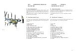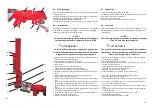
Fig. 3
CAP.3
DESCRIZIONE TECNICA DEL
SOLLEVATORE
3.1 Informazioni generali
Il sollevatore è stato progettato, realizzato e costruito, tenendo in consi-
derazione le esigenze operative degli addetti alle lavorazioni delle la-
miere delle autovetture, all’interno di ambienti di lavoro quali le carroz-
zerie.
Il sollevatore agevola il sollevamento delle autovetture permettendone
la salita senza l’ausilio di pedane.
3.2 Identificazione delle parti
Per quanto concerne la localizzazione delle parti principali che costitui-
scono il sollevatore, esse sono identificate nella fig. 3 {comprensivo di
accessori).
1. Telaio superiore
2. Basamento
3. Bracci di sollevamento
4. Cilindri oleodinamici per sollevamento
5. Staffe di supporto autovettura
6. Morse per aggancio auto
vettura
7. Staffa orizzontale braccio di
tiro
8. Braccio verticale
9. Ruote per movimentazione braccio di tiro
10. Catena con gancio e morsetto di fissaggi
11. Cavo di sicurezza per catena
12. Centralina di comando
13. Pulsantiera di comando
14. Pompa pneumatica per braccio di tiro (optional)
15. Cavallett
o
CHAPTER 3
TECHNICAL
DESCRIPTION OF THE LIFT
3.1 General information
The lift has been designed and made taking into consideration the ope-
rating needs of the people working the sheets of cars inside work envi-
ronments such as car body workshops
.
The lift facilitates lifting the car so it can be raised without the aid of
platforms.
3.2 Identification of the parts
As far as the location of the main parts that comprise the lift are concer-
ned they are identified in Fig. 3 {including accessories).
1. Top frame
2. Base
3. Lifting arms
4. Hydraulic cylinders for lifting
5. Vehicle supporting brackets
6. Vices to grip the vehicle
7. Horizontal pulling arm bracket
8. Vertical arm
9. Wheels to move the pulling arm
10. Chain with hook and fixing clamp
11. Safety cable for chain
12. Control unit
13. Control pushbutton panel
14. Pneumatic pump for pulling arm (optional)
15. Stand
.
15
7
8
9
4
3
2
5-6
1
10-11
14
12-13
15
Содержание RPK25/B
Страница 2: ......
Страница 22: ...SCHEMA ELETTRICO ELECTRIC WIRING SCHEME SCH MA LECTRIQUE ELEKTRISCHER ANSCHLUSSPLAN ESQUEMA EL CTRICO Fig 7...
Страница 53: ......
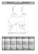
Страница 58: ...QUADRO ELETTRICO TRIFASE 3PH CONTROL PANEL SCHALTTAFEL DREHSTROM 3PH COFFRET LECTRIQUE 3PH CUADRO ELECTRICO 3PH...
Страница 59: ...CENTRALINA OLEODINAMICA OLEODYNAMIC CONTROL UNIT HYDRAULIKEINHEIT CENTRALE HYDRAULIQUE CENTRALITA HIDRAULICA...


