


87
Thus a driver receives information about the increase in steerable wheels turn resistance.
When the steering wheel is not turned (there is no effort on it) the torsion bar 17 and the
rams 21 return the slide valve to the neutral position. The fluid supply to the rod end of the
booster unit is stopped and the truck is driven in a circumferential direction of the set radius.
When the steering wheel is turned left, the bushing 9 with the slide valve 22 offset to the
right (away from the steering unit). The fluid is pumped to the groove «
е
», then through the
groove «c» to the rod end of the booster.
If the hydraulic booster is faulty, the back pressure valve 6 provides the by pass of oil
from one cavity of the booster unit to the other one which facilitates driving.
5.4.1.5 Steering Booster. The booster unit cushions the impact transferred to the steering
wheel when the truck is driven on a bumpy road, enhances driving safety, allows the truck to be
driven in the initial direction if the front tire is punctured, decreases the effort needed turning the
wheels.
The booster unit is connected with the frame and the rh lever of the front axle steering
knuckle by the joints. The rod length is adjusted in the range which provides the specified turn
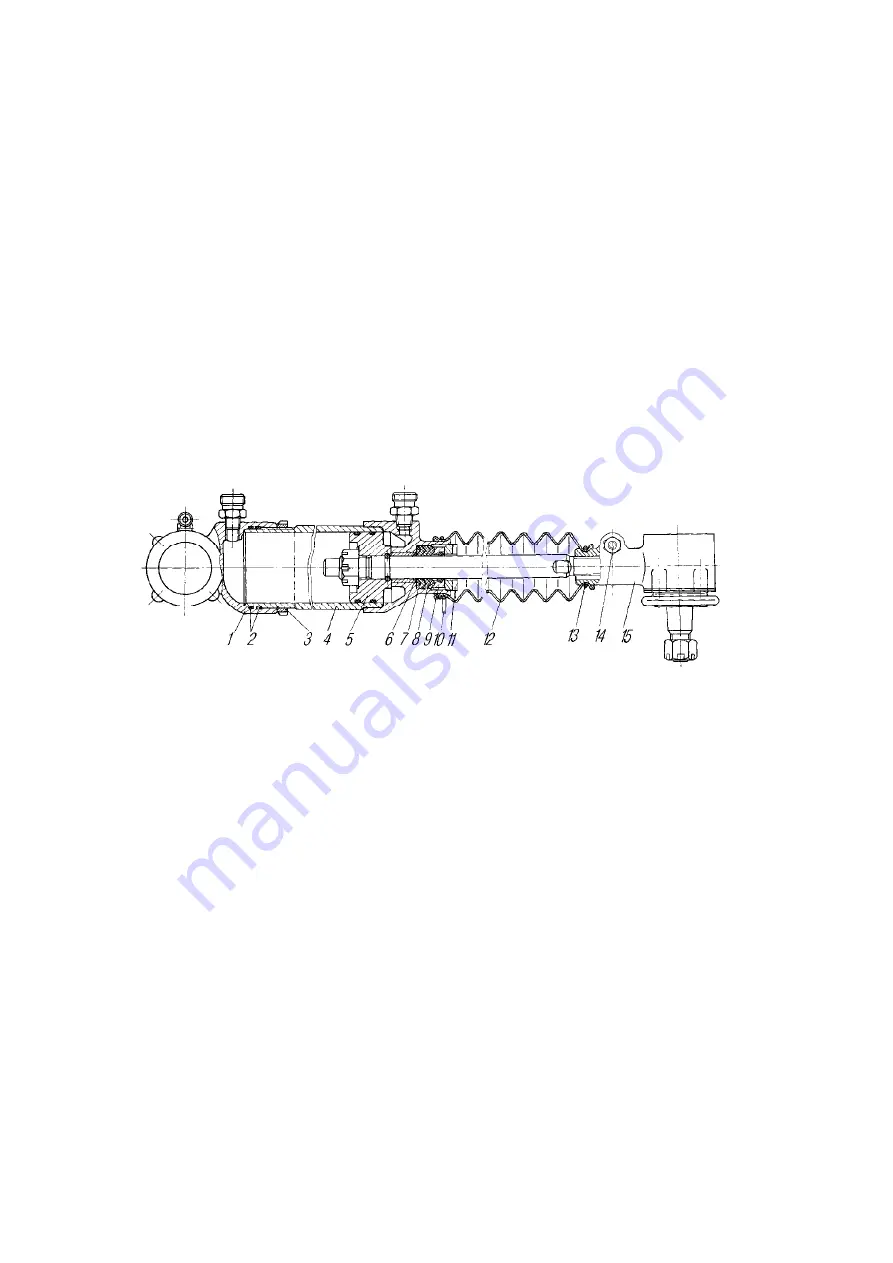
angles of the front wheels. To change the rod length, loosen the screw 14 (Fig. 63) of the end
clips, remove the protecting coupling 12 and rotate the rod with the wrench in any direction. If
there is leakage along the rod, compress the seal with the nut 11.
1-cylinder end; 2,6-packing rings; 3-rod end nut; 4-cylinder; 5-piston with rod; 7-supporting ring; 8-collar;
9-pressure ring; 10,13-attachment clips; 11-nut; 12-protecting coupling; 14-bolt; 15-rod end
Fig. 63. Booster unit
5.4.1.6 Booster Unit Pump. The booster unit pump (Fig. 64) is a blade-type and bilat-
eral. During pump shaft rotation the pump blades cling to the curved surface of the stator under
the action of centrifugal force and oil pressure under the stator. In the suction chambers the oil
flows into the space between the blades and is then expelled from the decreasing space with the
rotor wheel rotation.
The end surfaces of the casing and the distribution disk are polished. Nicks and burrs on
them as well as on the rotor, stator and the blades are not admissible. Two valves are located in
the pump cap. The bypass valve limits the amount of oil fed by the pump into the steering cylin-
der. The safety valve inside the bypass valve limits the oil pressure in the system, opening at the
pressure of 7,500-8,500 kPa (75-85 kgf/cm
2
). Control the hydraulic steering booster pump belt
tension with the force of 40 N (4 kgf) in the middle of the branch as indicated by the arrow «b».
The allowable deflection should be 7-13 mm. Adjust the belt tension with the square-shank
screw 13.
Содержание URAL-4320-60
Страница 1: ...URAL 4320 60 61 URAL 43206 61 URAL 5557 60 TRUCKS AND THEIR MODIFICATIONS ...
Страница 7: ...6 Fig 2 Ural 55571 60 Chassis Fig 3 Ural 43206 61 Truck ...
Страница 33: ...32 Fig 16 Ural 44202 0511 60 bolster trucks ...
Страница 147: ...146 Figure 123 Left side and right side safety guards ...


