background image

Technical specifications 


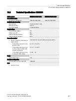
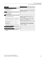
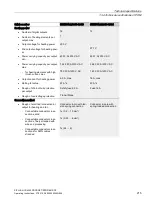
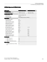
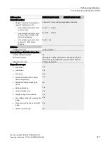
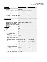
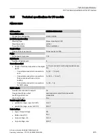
13.4 Technical specifications of POM 


SIPLUS HCS4200 PROFINET/PROFIBUS DP  

220


Operating Instructions, 07/2019, A5E35066204A/006 

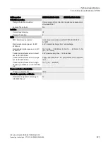
Article number 

6BK1942-2DA00-0AA0 

6BK1942-2FA00-0AA0 

Connection method 


Design of electrical connection for 

supply voltage 

Connector, 3-pole with spring-loaded connection 


Connectable conductor cross-

sections, solid 

1x (0.75 ... 16 mm²) 


Connectable conductor cross-

sections, finely stranded with 

wire end processing 

1x (0.75 ... 16 mm²) 


Connectable conductor cross-

sections for AWG cables 

1x (18 ... 4) 

Input voltage 


Design of the power supply 

Power supply via rack 

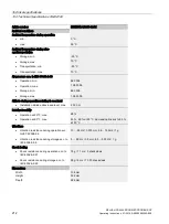
Power 


Active power input, max. 

1 W 

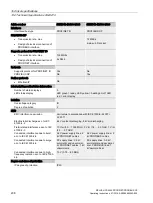
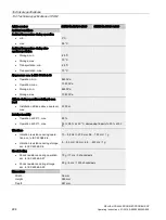
Power electronics 


Type of load 

Ohmic load 

Type of control of the heating elements  Half-wave control, phase 

control and soft start 

Half-wave control 

Power capacity, max. 

40 kW; At 400 V AC 

23 kW; At 230 V AC 


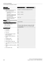
For phase against phase with fan at 

40 °C, max. 

40 kW; At 400 V AC 


For phase against phase without 

fan at 40 °C, max. 

12.5 kW; At 400 V AC 


For phase against neutral with fan 

at 40 °C, max. 

23 kW; At 230 V AC 


For phase against neutral without 

fan at 40 °C, max. 

7.3 kW; At 230 V AC 

Switching capacity current per phase, 

max. 

50 A 

Short-time withstand current (SCCR) 

acc. to UL 508A 


100 kA 

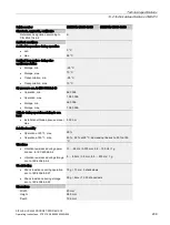
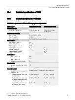
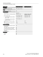
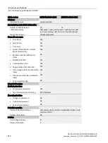
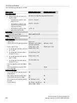
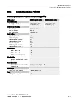
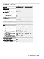
Load connection type 


Star connection with neutral conductor 

(single-phase) 

Yes 

Open delta connection (single-phase) 

Yes 

No 

Closed delta connection (3-phase) 

No 

Star connection with neutral conductor 

(2-phase) 

Yes; Economy circuit 

No 

2-pole switching 

Yes; Phase – neutral con-

ductor, phase – phase 

No 

Содержание SIPLUS HCS Series

Страница 1: ...SIPLUS HCS4200 PROFINET PROFIBUS DP ...

Страница 2: ......

Страница 3: ... 07 2019 A5E35066204A 006 Introduction 1 Security information 2 System overview 3 Application planning 4 Installation mounting 5 Connecting 6 Commissioning 7 Configuration 8 Functions 9 Communications 10 Process and system messages error handling 11 Service and maintenance 12 Technical specifications 13 Appendix A ...

Страница 4: ...d only by personnel qualified for the specific task in accordance with the relevant documentation in particular its warning notices and safety instructions Qualified personnel are those who based on their training and experience are capable of identifying risks and avoiding potential hazards when working with these products systems Proper use of Siemens products Note the following WARNING Siemens ...

Страница 5: ...utput Module POM 26 3 6 1 POM4220 26 3 6 2 POM4320 29 3 7 I O modules 30 3 7 1 PM4000 DI DO 30 3 7 2 PM4000 U I 31 3 7 3 PM4000 Temperature 32 4 Application planning 33 4 1 Shipping 33 4 2 Storage 33 4 3 Scope of delivery 34 4 4 Installation location 35 4 4 1 General requirements for the location of use 35 4 4 2 Double frame construction 40 4 4 3 Combined mode configuration 42 4 5 Power ratings 43...

Страница 6: ...lements and three phase line supply 79 6 6 1 Connecting the heating elements and three phase line supply 79 6 6 2 POM4220 Lowend block diagram 86 6 6 3 Block diagram POM4220 Midrange phase angle control and POM4220 Flexible 87 6 6 4 POM4220 Highend block diagram 88 6 6 5 Block diagram POM4320 93 6 7 Connecting I O modules 94 6 7 1 PM4000 DI DO 94 6 7 2 PM4000 U I 96 6 7 3 PM4000 Temperature 98 7 C...

Страница 7: ...arting function 135 9 3 4 Switch on heating 137 9 3 5 Soft start during heater operation 137 9 3 6 Channel control via setpoints 137 9 3 7 Channel control via fields 138 9 3 8 Line voltage compensation 139 9 3 9 Power control 140 9 3 10 Behavior of the power outputs 141 9 4 Digital inputs outputs 142 9 5 Recording of analog measured line values 143 9 5 1 Recording of analog measured line values wi...

Страница 8: ...80 11 2 1 LED operating display for POM 180 11 2 2 Fault reporting through diagnostics data 180 11 3 I O modules 182 12 Service and maintenance 185 12 1 Maintenance work 185 12 2 Firmware update 185 12 2 1 PROFINET firmware update 185 12 2 2 PROFIBUS firmware update 187 12 3 Fuse replacement 188 12 3 1 POM4220 Fuse Replacement 188 12 3 2 POM4320 Fuse Replacement 190 12 4 Replace fan 194 12 4 1 Rep...

Страница 9: ... 13 5 Technical specifications for I O module 235 13 6 Technical specifications for fan module 245 13 7 Technical specifications of expansion module EM4315 for combined mode only 247 13 8 Dimension drawings 250 13 8 1 HCS4200 components 250 13 8 2 HCS4300 components 253 A Appendix 257 A 1 Certificates and approvals 257 A 1 1 Certificates and approvals 257 A 2 Ordering data 258 A 3 ESD guidelines 2...

Страница 10: ...Table of contents SIPLUS HCS4200 PROFINET PROFIBUS DP 8 Operating Instructions 07 2019 A5E35066204A 006 ...

Страница 11: ...programmers Electrically skilled personnel who assemble connect and commission the device Required basic knowledge These operating instructions require prior knowledge of programming a SIMATIC S7 controller or SIMOTION Knowledge of working with the PROFINET PROFIBUS fieldbus is also necessary Naming conventions and abbreviations A synonym an abbreviation or the term device is sometimes used in thi...

Страница 12: ...5 Expansion for operation of 24 POMs and one I O module rack for 4 POMs connection to PROFIBUS DP 12 2016 Expansion with operation of POM4320 combined mode POM4220 Midrange phase angle control Configuration control option handling Commissioning support using PRONETA 10 2017 Expansion with POM4220 Highend and POM4220 Flexible 09 2018 Expansion with additional switching options and operating modes f...

Страница 13: ...e 169 The information that is read is always for the full configuration which means for 192 channels or 12 POMs The data records 160 190 and 202 are not available Notes for devices through FW version 2 0 of the CIM Configuration control is not available The POM4220 Midrange phase angle control cannot be configured No combination mode is supported Notes for devices through FW version 2 1 of the CIM...

Страница 14: ...Introduction 1 1 Introduction SIPLUS HCS4200 PROFINET PROFIBUS DP 12 Operating Instructions 07 2019 A5E35066204A 006 ...

Страница 15: ...er s warranty Warning symbols on the device WARNING Electric shock hazard May cause death or serious injury When this warning symbol appears on the device you must consult the operating instructions for the device The operating instructions contain information about the potential risks and enable you to recognize risks and implement countermeasures Note before connecting the device WARNING Electri...

Страница 16: ...ting contact must therefore be taken during commissioning and maintenance work Before working on the heating control system or the connected components ensure the system is disconnected Fuse replacement NOTICE Use only the prescribed fuse types If you operate a heating controller with unapproved fuses the device could be destroyed Repairs WARNING No user serviceable parts May cause death or seriou...

Страница 17: ... only be connected to an enterprise network or the internet if and to the extent such a connection is necessary and only when appropriate security measures e g firewalls and or network segmentation are in place For additional information on industrial security measures that may be implemented please visit Siemens products and solutions undergo continuous development to make them more secure Siemen...

Страница 18: ...Security information 2 2 Security information SIPLUS HCS4200 PROFINET PROFIBUS DP 16 Operating Instructions 07 2019 A5E35066204A 006 ...

Страница 19: ...ramic flash halogen or infrared heaters It is of modular design and can be flexibly adapted to suit the specific requirements of the respective application Typical application areas are Thermal treatment of fabrics and plastics Drying of enamels and paint coats PET blow molding Welding of plastic parts Handling of carbon materials In general the HCS4200 can be used wherever compact or modular conc...

Страница 20: ...aximum of 24 Power Output Modules POM As an option one I O module can be operated on the CIM Fan modules can be mounted on the rack Each fan module serves 4 slots or POMs Figure 3 1 Heating control system HCS4200 with rack for 12 4 POMs SIPLUS HCS4200 Compact HCS4200 Compact consists of a rack with integrated CIM4210 and two slots for Power Output Modules POM The fan is already mounted on the rack...

Страница 21: ...egrated fan not expandable I O module PM4000 DI DO 8 digital outputs 8 configurable inputs outputs PM4000 U I Inputs for measuring mains voltage and mains current PM4000 Temperature 4 analog inputs for 0 20 mA 4 measuring inputs for temperature Power Output Module POM4220 Lowend 230 V AC 16 power outputs 1449 W per power output POM4220 Midrange phase control 230 277 V AC 12 power outputs 4432 W pe...

Страница 22: ... with PRONETA Control modes POM4220 Lowend Half wave control POM4220 Midrange phase angle control and POM4220 Highend Half wave control Softstart and phase control POM4220 Flexible Half wave control Connection of incoming supply through 3 pole connector on the front of the POM Connection of power outputs via two connectors on the front of the POM Only a 24 V supply is needed for up to 12 POMs with...

Страница 23: ...system Figure 3 3 Example Combined mode HCS4200 with POM4320 The following additional system components are available System components Version Description Power Output Module POM POM4320 busbar mounting 9 power outputs with diagnostics and error display per channel POM4320 rear wall mounting Expansion module EM4315 Enables operation of up to 8 additional POMs Features Operation of up to 4 POMs pe...

Страница 24: ...s the following components Central Interface Module CIM4210 with PROFINET or PROFIBUS Power Output Module POM4220 Power Output Module POM4320 optional Rack Fan module optional Higher level controller e g SIMATIC S7 1500 automation system with PROFINET or PROFIBUS Field PG optional for commissioning and diagnostics Industrial PC optional e g Panel PC SIMATIC IPC 477D Heating field Figure 3 4 HCS420...

Страница 25: ...rial experience of PROFIBUS with the openness and flexible options of Ethernet PROFINET enables high speed and secure data exchange at all levels thus making it possible to implement innovative machine and plant concepts PROFIBUS has been established for years as the fieldbus for machines and plants Based on serial bus technology it is the foundation for the distributed concepts that are common to...

Страница 26: ...h PROFINET interface or with PROFIBUS interface CIM4210 PROFINET CIM4210 PROFIBUS Status LEDs Status LEDs System interface to installation frame rack System interface to installation frame rack PROFINET interface X1 X2 Address selector switches S1 and S2 for PROFIBUS 24 V DC supply X3 PROFIBUS DP interface X1 Service interface X2 Slot for I O module 24 V DC supply X3 Slot for I O module ...

Страница 27: ...erating Instructions 07 2019 A5E35066204A 006 25 CIM4210C The CIM4210C features a PROFINET interface and has two slots for Power Output Modules CIM4210C PROFINET Status LEDs PROFINET interface X1 X2 24 V DC supply X3 Integrated fan module Rack with two free slots for Power Output Modules ...

Страница 28: ... in TN and TT networks POM version Number of power outputs Output voltage Total contact rating POM4220 Lowend 16 230 V AC 16 1 kW POM4220 Midrange phase angle control 12 230 V AC 23 kW 277 V AC 27 7 kW POM4220 Highend 8 230 V AC 23 kW 277 V AC 27 7 kW 400 V AC 40 kW 480 V AC 48 kW POM4220 Flexible 12 45 V AC 4 5 kW 70 V AC 7 kW 110 V AC 11 kW 230 V AC 23 kW 277 V AC 27 7 kW You will find detailed ...

Страница 29: ...ing Instructions 07 2019 A5E35066204A 006 27 Design POM4220 Lowend POM4220 Midrange phase angle control Status LEDs Status LEDs Power outputs 1 8 Power outputs 1 6 Incoming supply Incoming supply Power outputs 9 16 Power outputs 7 12 Error LED for each channel Error LED for each channel ...

Страница 30: ...IBUS DP 28 Operating Instructions 07 2019 A5E35066204A 006 POM4220 Highend POM4220 Flexible Status LEDs Status LEDs Power outputs 1 4 Power outputs 1 6 Incoming supply Incoming supply Power outputs 5 8 Power outputs 7 12 Error LED for each channel Error LED for each channel ...

Страница 31: ...ower Output Module is available in different versions for busbar or panel mounting Configuration POM4320 for busbar mounting POM4320 for panel mounting Fans Fan Busbar adapter Mains connection L1 L2 L3 Protective conductor connection Protective conductor connection 3 x 3 power outputs including feedback error LED for each power output 3 x 3 power outputs including feedback error LED for each power...

Страница 32: ... The digital I O modules are controlled by the S7 CPU using the process image NOTICE The PM4000 DI DO may not be used for safety related functions Design PM4000 DI DO Item Description Status LEDs RUN LED lights up green Power on Initialization status ERR LED lights up red fault Digital outputs 1 to 8 Digital inputs outputs 9 to 16 switchable for each channel LED to display switching status one LED...

Страница 33: ...alue is calculated from the measured values Phase current measurement Three current transformers can be connected to the module L1 L2 L3 The rms effective value is calculated from the measured values The measuring accuracy depends on the current transformers used The measured values are transferred via the fieldbus and can be evaluated and further processed by the user Design PM4000 U I Item Descr...

Страница 34: ...r temperature in two wire technology or two measuring inputs for temperature in four wire technology Four analog inputs for 0 20 mA The measured values are transferred via the fieldbus and can be evaluated and further processed by the user Design PM4000 Temperature Item Description Status LEDs RUN LED lights up green Power on Initialization status ERR LED lights up red fault Analog inputs 1 to 4 M...

Страница 35: ...t the necessary protection against shock and impact 4 2 Storage It is absolutely essential that the device is stored in compliance with the storage conditions as described in Chapter Technical specifications Page 205 In the event of ingress of dirt or liquid into the equipment formation of condensation damage or any other failures to comply with the prescribed storage conditions the equipment must...

Страница 36: ... CIM4210 Compact Operating Instructions CD with license information CIM PROFINET 1 plug connector 2 pin HCS CIM4210C PROFINET Compact operating instructions CD with license information CIM PROFINET 1 plug connector 2 pin HCS FM4240 fan module Compact Operating Instructions HCS PM4000 Temperature Compact operating instructions 2 plug connectors 8 pin HCS PM4000 DI DO Compact operating instructions ...

Страница 37: ...g control system is designed for stationary installation in a control cabinet The rack forms the outer frame of the heating control system that you install in the control cabinet Installation location requirements WARNING Electric shock hazard May cause death or serious injury In order to reliably prevent hazards for the operating personnel the control cabinet must satisfy the following requiremen...

Страница 38: ...branch circuit fuse Observe the SCCR rating on the rating plate Only use the device in circuits limited accordingly Only use 60 75 C copper cables for the cabling Note Residual current protective device If a residual current protective device is provided for the mains supply a residual current circuit breakers of Type A with short time delay is sufficient for the HCS4200 If a residual current prot...

Страница 39: ...ng an HCS4200 NOTICE Damage due to overheating You must comply with all the instructions regarding the installation location and mounting position Otherwise the device may malfunction or incur permanent damage as a result of overheating Ensure that the permissible ambient temperature range is not exceeded see Section Technical specifications Page 205 Pollution degree SIPLUS HCS4200 is designed for...

Страница 40: ...power loss of a POM is calculated as follows POM version Constant power loss per POM Channel power loss POM4220 Lowend 1 W Pv 0 04 W A2 I2 0 8 W A I POM4220 Midrange phase control POM4220 Highend POM4220 Flexible 1 W Pv 0 02 W A2 I2 0 8 W A I You can find the power rating under POM4220 power rating Page 43 Power loss of POM4320 combined mode When planning and designing the cabinet cooling take int...

Страница 41: ...g operations as well as the duration of switching operations and pause times NOTICE Restriction of the switching power When using flash radiators with the following outputs switching operations can result in extremely high currents which trigger the channel fuses Over 750 W at 230 V AC with POM4220 Lowend Over 1600 W at 230 V AC with POM4220 Midrange phase angle control and POM4220 Flexible Over 2...

Страница 42: ...US DP 40 Operating Instructions 07 2019 A5E35066204A 006 4 4 2 Double frame construction Double frame construction The following combinations are allowed for the installation and assembly of racks Combination Side by side arrangement Side by side arrangement 4 12 12 12 12 4 4 4 ...

Страница 43: ...record See Acyclic output data Page 164 When mounting the frame stacked you need to observe a temperature derating of 10 C To control a fan at least one POM4220 must be mounted in the frame below Restrictions when using the POM4220 Highend Due to the power requirement of the POM4220 you cannot operate 24 POM4220 Highend at one CIM You can determine the maximum permitted number of POM4220 at one CI...

Страница 44: ... mode configuration Combined mode configuration HCS4200 heating control system can be combined with POM4320 as follows HCS4200 rack with 4 or 12 POM4220 4 POM4320 Figure 4 2 HCS4200 combined mode combination option 1 HCS4200 rack with 4 or 12 POM4220 4 POM4320 1 EM4315 expansion module 8 POM4320 Figure 4 3 HCS4200 combined mode combination option 2 ...

Страница 45: ...uctions 07 2019 A5E35066204A 006 43 4 5 Power ratings The power ratings apply if the component HCS Rack4200 is used Derating does not apply if the CIM4210C PROFINET is used 4 5 1 POM4220 power rating Power rating of the POM4220 Lowend 230 V Figure 4 4 Power rating of the POM4220 Lowend 230 V ...

Страница 46: ...IBUS DP 44 Operating Instructions 07 2019 A5E35066204A 006 Power rating of the POM4220 Midrange phase angle control POM4220 Highend and POM4220 Flexible 230 V Figure 4 5 Power rating of the POM4220 Midrange phase angle control POM4220 Highend and POM4220 Flexible 230 V ...

Страница 47: ...IBUS DP Operating Instructions 07 2019 A5E35066204A 006 45 Power rating of the POM4220 Midrange phase angle control POM4220 Highend and POM4220 Flexible 277 V Figure 4 6 Power rating of the POM4220 Midrange phase angle control POM4220 Highend and POM4220 Flexible 277 V ...

Страница 48: ...g 4 5 Power ratings SIPLUS HCS4200 PROFINET PROFIBUS DP 46 Operating Instructions 07 2019 A5E35066204A 006 Power rating of the POM4220 Highend 400 V and 480 V Figure 4 7 Power rating of the POM4220 Highend 400 V and 480 V ...

Страница 49: ...g 4 5 Power ratings SIPLUS HCS4200 PROFINET PROFIBUS DP Operating Instructions 07 2019 A5E35066204A 006 47 Power rating of the POM4220 Highend 2 pin switching Figure 4 8 Power rating of the POM4220 Highend 2 pin switching ...

Страница 50: ... planning 4 5 Power ratings SIPLUS HCS4200 PROFINET PROFIBUS DP 48 Operating Instructions 07 2019 A5E35066204A 006 Power rating of the POM4220 economy circuit Figure 4 9 Power rating of the POM4220 economy circuit ...

Страница 51: ...nstructions 07 2019 A5E35066204A 006 49 Power rating of the POM4220 Flexible 45 V 70 V and 110 V Figure 4 10 Power rating of the POM4220 Flexible 45 V 70 V and 110 V Temperature derating with double frame Note With stacked mounting of the racks a temperature derating of 10 C is required ...

Страница 52: ...ation planning 4 5 Power ratings SIPLUS HCS4200 PROFINET PROFIBUS DP 50 Operating Instructions 07 2019 A5E35066204A 006 4 5 2 POM4320 power rating POM4320 IEC power rating Figure 4 11 POM4320 IEC power rating ...

Страница 53: ...Application planning 4 5 Power ratings SIPLUS HCS4200 PROFINET PROFIBUS DP Operating Instructions 07 2019 A5E35066204A 006 51 Power rating POM4320 UL Figure 4 12 POM4320 UL power rating ...

Страница 54: ...Application planning 4 5 Power ratings SIPLUS HCS4200 PROFINET PROFIBUS DP 52 Operating Instructions 07 2019 A5E35066204A 006 ...

Страница 55: ... damage to property Dangerous voltages may be present in the control cabinet Before work starts on mounting and connecting the HCS4200 heating controller you must implement safety measures to prevent any touching 5 2 Mounting the rack Preparations WARNING Electric shock hazard May cause death or serious injury Before installation work starts switch off the power supply to the control cabinet and s...

Страница 56: ...wing sequence Figure 5 1 Installing a rack Steps 1 Drill the threads for the M6 fixing screws in the mounting plate The positions of the pre fabricated mounting holes on the rack are shown in the drill hole tem plate see figure below 2 Screw the fixing screws into the mounting plate but do not tighten 3 Position the rack in the control cabinet 4 Screw the rack firmly into place ...

Страница 57: ...019 A5E35066204A 006 55 Dimensions and distance between holes for installation on mounting plate Figure 5 2 Rack4200 for 12 POMs Dimensions and distance between holes for installation on mounting plate Figure 5 3 HCS Rack4200 for 4 POMs Dimensions and distance between holes for installation on mounting plate ...

Страница 58: ...en the two fastening screws on the fan module but do not remove them 2 Pull the connecting cable through the opening in the rack 3 Place the fan module on the rack and lift it at the rear until the screw heads fit through the two keyholes Push the fan module forward until the two tabs pass through the corresponding openings Lower the fan module at the rear keyhole and tighten the fastening screws ...

Страница 59: ... need a Torx T10 screwdriver Installing a central interface module The Central Interface Module is screwed directly to the rack The mounting steps are described below Figure 5 5 Mounting the CIM Steps 1 The fixing screws are screwed into the CIM in the delivery condition Loosen the six fixing screws 2 Connect the connector of the system interface to the CIM 3 Place the CIM on the rack and fasten i...

Страница 60: ...O module Note The I O module may only be inserted or removed when the power is off Tool You will need a Torx T8 screwdriver Installing an I O module The steps for mounting an I O module are described below Figure 5 6 Installing an I O module Steps 1 Dismantling the blanking cover of the receptacle on the CIM 2 Insert the I O module into the receptacle and push it in as far as it will go 3 Secure m...

Страница 61: ...wer output module Tool You will need a Torx T8 screwdriver Mounting the POM The procedure for mounting the POM is described below Figure 5 7 Mounting the POM Steps 1 Slide the POM into the rack 2 Screw in place at the top and bottom of the front plate NOTICE Possible damage of the POM Make sure to insert the POM straight and not tilted because the POM may be damaged otherwise ...

Страница 62: ...0C PROFINET Mounting CIM4210C PROFINET Figure 5 8 Installing CIM4210C 1 Drill 4 threaded holes M6 in the mounting plate The threaded holes are shown in the section HCS4200 components Page 250 2 Screw 4 screws M6 in the mounting plate 3 Insert the device in the control cabinet 4 Fasten the device Dismantling CIM4210C PROFINET 1 Loosen the 4 screws 2 Remove the device from the control cabinet ...

Страница 63: ...king cover over the appropriate slot 2 Screw the blanking cover to the rack with two screws top and bottom 5 9 Double frame setup The following describes how to set up a double frame Modifications to the lower frame 1 Release retaining clip on the right hand CIM side by pressing on the interlock 2 Feed the ribbon cable through the opening to the back 3 By releasing and setting the ribbon cable cli...

Страница 64: ...4200 PROFINET PROFIBUS DP 62 Operating Instructions 07 2019 A5E35066204A 006 On the upper frame fold the ribbon cable back and insert it into the plug connector To secure it use the spare retaining clip from the top frame Figure 5 10 Double frame completed ...

Страница 65: ...m May cause death serious injury or damage to property Dangerous voltages can be present on the busbar system The busbar system must therefore be isolated and secured against reclosing before work begins for mounting and connecting the HCS4300 heating control system NOTICE Clockwise rotating field When connecting the busbar system make sure that the energy system is connected clockwise Note Residu...

Страница 66: ...mm Adjusting the busbar adapter to the thickness of the busbar The busbar adapter of the POM can be adjusted for the following busbar thicknesses 5 mm delivery state 10 mm On the busbar adapter of the POM there are four fastening blocks which you can use to adjust the busbar adapter to the rail thickness The following figure shows the position of the fastening blocks POM busbar adapter Fastening b...

Страница 67: ...erating Instructions 07 2019 A5E35066204A 006 65 Proceed as follows for each of the four fastening blocks Steps 1 Use the screwdriver to push out the fas tening block 2 Position the fastening block in accordance with the rail thickness 5 mm 10 mm 3 Push the fastening block back until it latch es in place ...

Страница 68: ...ing of the POM on the busbar is carried out without the need for tools via the POM busbar adapter Installing the POM Figure 5 11 Installing the POM Steps 1 Press the button on the top of the busbar adapter The holder must protrude beyond the busbar adapter as shown in the figure 2 Place the busbar adapter on the busbar from above 3 Press on the busbar adapter from above until the busbar adapter en...

Страница 69: ... mounting Installing the Power Output Modul POM 1 Predrill the holes in the rear panel for mounting The required hole spacing is shown in the diagram below 2 Screw the POM into place on the rear panel with four screws M5 Figure 5 12 POM4320 Position of the mounting holes Minimum spacing Natural convection must be possible above and below the device A clearance of 100 mm must be observed in both ca...

Страница 70: ...Installation mounting 5 10 Mounting a POM4320 power output module SIPLUS HCS4200 PROFINET PROFIBUS DP 68 Operating Instructions 07 2019 A5E35066204A 006 ...

Страница 71: ... cause death or serious injury The mains supply to which the device is connected must have a circuit breaker or a fuse The circuit breaker or fuse must be easily accessible and clearly assigned to the device We recommend locating the circuit breaker or fuse near to the device Take the maximum current consumption of the heating control system into consideration when selecting the circuit breaker or...

Страница 72: ...m or the connected components ensure the system is disconnected CAUTION High levels of leakage current Risk of injury Before connecting the device to the supply system you must connect the grounding circuit see Section Connecting the protective conductor Page 71 Connection requirements The device has been mounted The mains supply is disconnected at the mounting location of the device and secured a...

Страница 73: ...or serious injury The protective conductor must be connected to the threaded pin indicated HSC4200 The cable cross section for the protective conductor must be 10 mm2 HSC4300 The cable cross section for the protective conductor must be 16 mm2 The cable lug used must have a tin coated surface to ensure corrosion protection When connecting the protective conductor the applicable national and local r...

Страница 74: ...ive and grounded If this is not the case you must ground the frame for a second time at a mounting hole If the rear panel is not metallically conductive and not grounded the leakage current may be too high and there is a risk of danger to life Connect the rack to the protective conductor PE You will find an M6 threaded bolt on the right side of the rack for this purpose The retaining elements nut ...

Страница 75: ...st ground the frame for a second time at a mounting hole If the rear panel is not metallically conductive and not grounded the leakage current may be too high and there is a risk of danger to life 1 Connect the CIM4210C to the protective conductor PE There is a threaded pin M6 for connecting the protective conductor at the front of the CIM4210C Connecting a protective conductor to POM4320 1 Connec...

Страница 76: ...Combined mode with POM4320 Connecting system interfaces Connecting system interface Connecting system interfaces racks to POM Attach the connecting cable between the rack and POM Additional POM can be con nected with a ribbon cable to the preceding POM You can operate up to 4 POM4320 without expansion module on a rack Connect ing cable see Ordering data Page 258 ...

Страница 77: ... Attach the connecting cable from the rack to the system interface of the EM4315 Additional POM can be con nected with a ribbon cable to the preceding POM The operation of up to 8 additional POM is possible with an EM4315 expansion module Note The last bus connector remains open on the last POM4320 NOTICE The total length of all connecting cables at the system interface rack EM4315 must not exceed...

Страница 78: ...ct X1 and X2 to the higher level controller and or the next PROFINET device using an Ethernet cable according to the PROFINET specification Connect PROFIBUS and set the PROFIBUS address CIM PROFIBUS connection X1 Assign the PROFIBUS address using the S1 and S2 address selector switches Addresses can be set from 0 to 99 Connect X1 to the higher level controller and or the next PROFIBUS device via c...

Страница 79: ... system interface Layout of the 24 V DC power supply You can determine the layout of the 24 V DC power supply using the following calculation formula Minimum power rating 3 W Number of POM4220 Lowend POM4220 Midrange phase angle control POM4220 Flexible 1 W Number of POM4220 Highend 1 5 W Number of fan modules 10 W Number of I O modules 1 W Example Supply of an HCS4200 comprising a rack CIM PROFIN...

Страница 80: ...wing applies An external lightning protection element should be connected upstream in the 24 V DC supply line Dehn Blitzductor BVT type AD24 No 918402 or equivalent When using other items you must ensure that the model used is equivalent consult with lightning protection manufacturer The lightning protection module must be installed and used in accordance with the manufacturer s specifications Wit...

Страница 81: ...ting elements and three phase line supply Connecting the heating elements and three phase line supply POM4220 The heating elements are connected by means of two plug connectors at X1 and X3 of the POM POM4220 Lowend Two 8 pin plug connectors POM4220 Midrange phase angle control and POM4220 Flexible Two 6 pin plug connectors POM4220 Highend Two 4 pin plug connectors The 3 phase line is connected by...

Страница 82: ... The plug connectors for the heating elements and the power connection are included in the scope of supply of the heating control system Features Spring loaded terminal and automatic tool free interlock To unlock press down the two levers on the sides of the plug connectors To lock the plug connector in place correctly press it in by the plug body and not by the gray unlatching wedge If end sleeve...

Страница 83: ... supply SIPLUS HCS4200 PROFINET PROFIBUS DP Operating Instructions 07 2019 A5E35066204A 006 81 POM4220 Lowend Pin assignment X1 to X3 X1 8 pin connector for power output 1 8 X2 3 pin connector for line connection phase LX1 N LX3 X3 8 pin connector for power output 9 16 ...

Страница 84: ... PROFINET PROFIBUS DP 82 Operating Instructions 07 2019 A5E35066204A 006 POM4220 Midrange phase angle control and POM4220 Flexible Pin assignment X1 to X3 X1 6 pin connector for power output 1 6 X2 3 pin connector for line connection phase LX1 N LX3 X3 6 pin connector for power output 7 12 ...

Страница 85: ... supply SIPLUS HCS4200 PROFINET PROFIBUS DP Operating Instructions 07 2019 A5E35066204A 006 83 POM4220 Highend Pin assignment X1 to X3 X1 4 pin connector for power output 1 4 X2 3 pin connector for line connection phase LX1 N LX3 X3 4 pin connector for power output 5 8 ...

Страница 86: ...66204A 006 POM4320 Position of the connections Pin assignments X1 to X6 X1 3 pin plug for L1 Power output 1 3 outgoing X2 3 pin plug for L2 Power output 4 6 outgoing X3 3 pin plug for L3 Power output 7 9 outgoing X4 3 pin plug for L2 Power output 1 3 incoming X5 3 pin plug for L3 Power output 4 6 incoming X6 3 pin plug for L1 Power output 7 9 incoming ...

Страница 87: ... connect the POM4320 to the three phase supply pay attention to the rotating field running clockwise Note that you must use two different phases when connecting a POM4220 Highend Figure 6 1 Wiring diagram for three phase system Block wiring diagrams The block diagrams below show the main circuits of the POM4220 versions with power and heating element connections The power outputs are protected int...

Страница 88: ...ating elements and three phase line supply SIPLUS HCS4200 PROFINET PROFIBUS DP 86 Operating Instructions 07 2019 A5E35066204A 006 6 6 2 POM4220 Lowend block diagram POM4220 Lowend power outputs Figure 6 2 POM4220 Lowend power outputs ...

Страница 89: ...ET PROFIBUS DP Operating Instructions 07 2019 A5E35066204A 006 87 6 6 3 Block diagram POM4220 Midrange phase angle control and POM4220 Flexible Power outputs POM4220 Midrange phase angle control and POM4220 Flexible Figure 6 3 Power outputs POM4220 Midrange phase angle control and POM4220 Flexible ...

Страница 90: ... line supply SIPLUS HCS4200 PROFINET PROFIBUS DP 88 Operating Instructions 07 2019 A5E35066204A 006 6 6 4 POM4220 Highend block diagram Connection between phase and neutral conductor Figure 6 4 Power outputs POM4220 Highend connection between phase and N conductor ...

Страница 91: ...P Operating Instructions 07 2019 A5E35066204A 006 89 Connection between phase and phase Figure 6 5 Power outputs POM4220 Highend Connection between phase and phase Note The following applies to connections between phase and phase The heating elements must be switched to the other connected phase of the module ...

Страница 92: ...ne of the two main power semiconductors short circuit operation is still possible or the load can be turned off With this type of connection only channels 1 to 4 are used Figure 6 6 POM4220 Highend power outputs 2 pin connection between phase and neutral conductor Please note the particularities of this type of connection regarding the following aspects Configuration parameters see Configuration p...

Страница 93: ...e of the two main power semiconductors short circuit operation is still possible or the load can be turned off With this type of connection only channels 1 to 4 are used Figure 6 7 POM4220 Highend power outputs 2 pin connection between phase and phase Please note the particularities of this type of connection regarding the following aspects Configuration parameters see Configuration parameters for...

Страница 94: ...e used Radiators with tungsten heating coils for example are not permitted With this type of connection only channels 1 to 4 are used Note A three pin triangular load cannot be operated on the POM4220 Highend Figure 6 8 Power outputs POM4220 Highend Economy circuit Please note the particularities of this type of connection regarding the following aspects Configuration parameters see Configuration ...

Страница 95: ...ing Instructions 07 2019 A5E35066204A 006 93 6 6 5 Block diagram POM4320 Block diagram The following figure shows the basic wiring of the POM4320 heating control system with mains and heating element connection The power outputs are protected internally with two fuses per power output Figure 6 9 POM4320 power outputs ...

Страница 96: ...ns 07 2019 A5E35066204A 006 6 7 Connecting I O modules 6 7 1 PM4000 DI DO Connecting the digital inputs outputs The connection is made by means of two 18 pin plug connectors of the PM4000 DI DO Figure 6 10 PM4000 DI DO pin assignment Note The connection cables are to be shielded if longer than 30 m ...

Страница 97: ... connection and interlock The mating connectors are included in the scope of supply Pin Assignment Pin 1 GND Digital output 1 2 3 GND Digital output 2 4 5 GND Digital output 3 6 7 GND Digital output 4 8 9 GND Digital output 5 10 11 GND Digital output 6 12 13 GND Digital output 7 14 15 GND Digital output 8 16 17 GND P24 18 X2 Digital inputs outputs 18 pin connector with spring loaded connection and...

Страница 98: ...ts Connecting to mains power is done via the 8 pin plug in connector X1 of the PM4000 U I Connecting to mains voltage is done via the 6 pin plug in connector X2 of the PM4000 U I WARNING Voltage hazards Danger to life Before working on the heating control system or the connected components ensure the system is disconnected Figure 6 11 Line measurement inputs pin assignment ...

Страница 99: ...ectors are included in the scope of supply Pin Assignment Pin 1 I1 I1 2 3 I2 I2 4 5 I3 I3 6 7 Reserved Reserved 8 Note The connection cable for the current measurement must not be longer than 30 m X2 Voltage measurement 6 pin connector with spring loaded connection and interlock The mating connectors are included in the scope of supply Pin Assignment 1 Reserved 2 Phase 1 3 Phase 2 4 Phase 3 5 Neut...

Страница 100: ...emperature The measurement inputs for temperature are connected by means of the 8 pin plug connector X2 of the PM4000 Temperature Figure 6 12 PM4000 Temperature pin assignment X1 Four analog inputs 0 20 mA 8 pin connector with spring loaded connection The mating connectors are included in the scope of supply Pin Assignment Pin 1 Analog channel 1 Analog channel 1 2 3 Analog channel 2 Analog channel...

Страница 101: ...annel 1 Temperature channel 1 2 3 Temperature channel 2 Temperature channel 2 4 5 Temperature channel 3 Temperature channel 3 6 7 Temperature channel 4 Temperature channel 4 8 4 wire measurement Pin Assignment Pin 1 Temperature channel 1 U Temperature channel 1 U 2 3 Temperature channel 1 I Temperature channel 1 I 4 5 Temperature channel 3 U Temperature channel 3 U 6 7 Temperature channel 3 I Temp...

Страница 102: ...Connecting 6 7 Connecting I O modules SIPLUS HCS4200 PROFINET PROFIBUS DP 100 Operating Instructions 07 2019 A5E35066204A 006 ...

Страница 103: ...th PROFINET PROFIBUS interface A SIPLUS HCS4200 heating controller consisting of the components Rack Central Interface Module CIM At least one Power Output Module POM 7 2 Commissioning Procedure 1 Turn on the 24 V DC power supply 2 Switch on the AC power supply The CIM and POM components of the heating control system start up 3 Observe the operating state indicators see Chapter Process and system ...

Страница 104: ... phase angle control POM4220 Flexible POM4220 Highend The specified protective conductor current refers to the output channels of one phase of a POM 230 V 50 Hz 1 9 mA 12 8 mA 277 V 50 Hz 2 3 mA 15 4 mA POM4320 Because of the protective impedances in the device the isolation resistance of a device of each phase to ground with an open load is around 124 kΩ and around 70 kΩ with connected heating lo...

Страница 105: ...ortal and can be downloaded from the Siemens Service Support area http www siemens com automation service support Procedure with non Siemens controllers For PROFINET configuration you will need the language specific GSDML file The GSDML file must be installed in the configuration software The GSDML file GSDML V2 34 Siemens 002A HCS4200 yyyymmdd can be downloaded from the Siemens Service Support ar...

Страница 106: ...d by installing the GSD file This is available in the following language versions German SIEM81C4 gsg and English SIEM81C4 gse and can be downloaded from the Service Support area http www siemens com automation service support Procedure with non Siemens controllers You will need the language specific GSD file for PROFIBUS configuration The SIEM81C4 gsx files can be downloaded from the Siemens Serv...

Страница 107: ... PROFINET IO 2 3 4 n 1 CIM head Subslot 1 1 I O module Subslot 1 2 The configuration rules are as follows CIM Slot 0 represents the PROFINET connection with the two ports The CIM provides a slot for an I O module The CIM module and the CIM I O module are assigned to slot 1 and are designed as submodules If an I O module is not used subslot 1 2 remains empty POM A maximum of 24 POMs can be operated...

Страница 108: ... 1 1 Head 1 2 PM The configuration rules are as follows CIM Slot 0 represents the PROFINET connection with the two ports The CIM provides a slot for an I O module The CIM module and the CIM I O module are assigned to slot 1 and are designed as submodules If an I O module is not used subslot 1 2 remains empty POM A maximum of 12 POM4220 and 12 POM4320 can be operated on one CIM Note When using a 4x...

Страница 109: ...esent in slot 2 If no I O module PM is used an empty space must be configured here POM A maximum of 12 POMs can be operated on one CIM NOTICE No startup possible If the device configuration in the project engineering does not match the configuration of the HCS that actually exists the device does not start up Ensure that the device configuration and the configuration that actually exists match Res...

Страница 110: ...and during re parameterization Configuration parameters CIM Description Value range Rated voltage for line voltage com pensation The permitted value depends on the used POM versions see Line voltage compensation Page 139 Configuration control switched on No default Yes Configuration parameters POM4220 Lowend Description Value range Control type setting once per POM Half wave control default Phase ...

Страница 111: ...annel substitute value 0 default Channel value is retained Configuration parameters POM4220 Midrange phase angle control Description Value range Control type setting once per POM Half wave control default Half wave control with soft start version 1 Half wave control with soft start version 2 Half wave control with soft start version 3 Phase angle control Phase angle control with Softstart version ...

Страница 112: ... phase and phase Economy circuit1 Phase LX12 setting once per POM Connected default Not connected Phase LX32 setting once per POM Connected default Not connected Soft start for each channel switch on operation setting once per POM No default Yes Enable output control setting once per POM No default Yes Enable fault current monitoring setting once per POM No default Yes Threshold for fault current ...

Страница 113: ...oad 230 V Uload 2 Load with Urated 240 V Prated 1500 W Pnormalized 1500 W 230 V 240 V 2 Pnormalized 1378 W Calculation example for interconnection phase phase Normalization Pscaled Pload 400 V Uload 2 Load with Urated 480 V Prated 6000 W Pnormalized 6000 W 400 V 480 V 2 Pnormalized 4167 W Configuration parameters POM4320 Description Value range Control mode Set once per POM Half wave control defau...

Страница 114: ...alog channel 1 measuring range Analog channel 4 measuring range Not connected default 0 20 mA 4 20 mA open circuit detection Temperature channel 1 sensor type Temperature channel 3 sensor type None default Pt 100 Pt 100 four wire Pt 1000 Pt 1000 four wire Type J thermocouple Type K thermocouple Type L thermocouple Temperature channel 2 sensor type Temperature channel 4 sensor type None default Pt ...

Страница 115: ...nnel 16 Input default Output Output 1 Response to errors Output 16 Response to errors Shutdown default Keep last value Switching on Alarm on open circuit No default Yes Note If power outage monitoring is enabled unused outputs must be closed or controlled with 1 Alarm on absence of 24 V power supply No default Yes Parameter PM4000 U I Description Value range Type of voltage connection Star default...

Страница 116: ... block library for the TIA Portal are available for the SIMATIC S7 1500 automation system to support commissioning of the heating control system HTML pages SIMATIC S7 SIMATIC controllers with PROFINET interface e g S7 1500 have an integrated web server that contains web pages for displaying diagnostics data This web server can be accessed via a standard web browser This supports scanning and savin...

Страница 117: ...odule configuration of the components By reading and writing the inputs and outputs PRONETA makes sure that the distributed I O devices with their sensors and actuators are correctly wired PRONETA can create test profile templates and store test logs to document the test results All tasks can be performed even before a CPU is integrated into the network Moreover since no other engineering tools or...

Страница 118: ...ed not be modified and it is not necessary to load a modified configuration Using a custom control data record you inform the HCS which modules in a station option are missing or are located in a different slot as compared to the station master The configuration control does not have an impact on the parameter assignment of the modules The following figure shows 3 expansion levels of a heating con...

Страница 119: ...e the Configuration control on parameter 8 5 3 Controller 8 5 3 1 Slot assignment Slot assignment The following table shows the possible slots for the various modules Table 8 3 Slot assignment Modules Possible slots Note CIM PN 0 The PN connection of the CIM is not an element of the configuration control CIM 1 1 The header of the CIM subslot is not an element of the configuration control but inste...

Страница 120: ... rejected Rules Observe the following rules The entry for slot 1 only identifies the PM see also Table 8 3 Slot assignment Page 117 All modules up to the max possible configuration of the HCS must be registered in control data record The entries up to at least the last slot of the station master must be contained in the control data record Entries beyond the last slot must be pre assigned with Mod...

Страница 121: ...the following rule If the module is included in the station option enter the slot num ber of the module from the station master If the slot in the station master is not allocated e g empty slots as part of combined operation then enter the slot number of the module 128 Example module as empty slot on slot 3 Enter 131 in the control ele ment If the module does not exist in the station option enter ...

Страница 122: ...rol data record is not sent it is assumed that no modules are inserted DS197 has status 0 Feedback data record Table 8 5 Feedback data record Byte Element Code Explanation 0 Block length 4 number of slots x 2 Header 1 Block ID 197 2 Version 2 3 0 4 Slot 1 status 0 1 Status 1 Module from station master is in serted in the station option Slot is marked as not available in the control data record Sta...

Страница 123: ...e STEP 7 online help ID Hardware identifier INDEX Data record number 196 decimal RECORD Control data record to be transferred For the structure of the control data record see table Page 118 In case of error the instruction WRREC returns the following error messages via the STATUS block parameter Table 8 6 Error messages WRREC Error code Meaning 80B1H Invalid length the length information in data r...

Страница 124: ...ter error The following events cause a parameter error Incorrect block ID in the header not equal to 197 Invalid version identifier in the header A reserved bit was set Multiple slots in the station master are assigned to the same slot in the station option Special requirements relating to the transfer of the control data record If you have enabled configuration control the HCS is not ready for op...

Страница 125: ...not supply diagnostics and their status is always OK The value status is OK Direct write access to the outputs that are not present or write access to the process image of the outputs that are not present Remains without effect no access error is signaled Direct read access to the inputs that are not present or read access to the process image of the inputs that are not present Value 0 is supplied...

Страница 126: ... control 8 5 4 1 Station master HCS4200 Station master HCS4200 In the following a station master comprising an CIM4210 PM Temp two POM4220 low end and POM4220 mid range each is configured Figure 8 2 Station master HCS4200 With configuration control the following station options are derived from the station master Station option with no PM Figure 8 3 Station option with no PM ...

Страница 127: ...0 Module not available 28 Slot 25 of station master 0 Module not available The data record can also be written in abbreviated form with length 4 5 the last entry is byte 8 in this case If there are no errors the feedback data record DS197 contains the following entries Byte Element Code Description 0 Block length 4 50 Header 1 Block ID 197 2 Version 2 3 Version 0 4 Slot 1 of station master 1 Modul...

Страница 128: ...25 Header 1 Block ID 196 2 Version 1 3 Version 0 4 Slot 1 of station master 1 PM available 5 Slot 2 of station master 2 POM available 6 Slot 3 of station master 3 POM available 7 Slot 4 of station master 0 POM is not inserted in the station options 8 Slot 5 of station master 0 POM is not inserted in the station options 9 Slot 6 of station master 0 Module not available 28 Slot 25 of station master ...

Страница 129: ... 4 50 Header 1 Block ID 197 2 Version 2 3 Version 0 4 Slot 1 of station master 1 Module is actually available 5 Slot 2 of station master 1 Module is actually available 6 Slot 3 of station master 1 Module is actually available 7 Slot 4 of station master 1 Module is actually not available 8 Slot 5 of station master 1 Module is actually not available 9 Slot 6 of station master 1 Module is actually no...

Страница 130: ...ined mode Station master HCS4200 combined operation In the following a station master is configured comprising an CIM4210 one POM4220 low end and one POM4220 mid range each two POM4320s Figure 8 5 Station master HCS combi With configuration control the following station option was derived from the station master Station option with no POMs Figure 8 6 Station option with no POMs ...

Страница 131: ...station master 0 Module not available 28 Slot 25 of station master 0 Module not available The data record can also be written in abbreviated form with length 4 5 the last entry is byte 8 in this case If there are no errors the feedback data record DS197 contains the following entries Byte Element Code Description 0 Block length 4 50 Header 1 Block ID 197 2 Version 2 3 Version 0 4 Slot 1 of station...

Страница 132: ...Configuration 8 5 Configuration control option handling SIPLUS HCS4200 PROFINET PROFIBUS DP 130 Operating Instructions 07 2019 A5E35066204A 006 ...

Страница 133: ...d startup of the channels x x x x Soft start during heater operation x Channel control over setpoints x x x x Channel control over fields x x x x Line voltage compensation x1 x1 x x Power control x Parameter assignment of behavior of the power outputs x x x x Phase control monitoring x x x x Rotating field test x2 x Line voltage monitoring x1 x1 x x Frequency monitoring x x x x Temperature monitor...

Страница 134: ...meaning of the LED displays see Section LED operating display for CIM Page 179 and Section LED operating display for POM Page 180 9 3 Power output control 9 3 1 Half wave control Half wave control can be parameterized for activating the heating elements This parameterization is performed for each POM and applies to all channels of the POM Operating principle of half wave control The power outputs ...

Страница 135: ...time delayed See Switch on heating Page 137 A static table is used for control so that a too frequent change of the setpoints can result in a significantly deviating setpoint For this reason the setpoints are only forwarded in a time scale of ca 600 ms Note If it is required for an application that a changed setpoint value is applied immediately you can switch off this time grid see Acyclic output...

Страница 136: ...alf wave The HCS specifies the switch on signal at the corresponding time in every half wave depending on the setpoint for the Triac which is then switched on until the next zero crossing Figure 9 2 Phase control The setpoints for controlling the power outputs are within a value range of 0 to 100 reference value U2 To avoid excessively high inrush currents the power outputs are switched on time de...

Страница 137: ...hannels of the POM Soft start means that the channels when turned on with a certain number of half waves are controlled with phase angle control before being switched to half wave operation or phase angle control Figure 9 3 Soft starting function Note The disturbances caused on the supply cables by the soft starting are to be filtered on the line side For suitable filters see the note in the secti...

Страница 138: ...d for one channel is about 500 ms for POM4220 and 100 ms for POM4320 2 Slower version of the soft start that ensures the heating element is not unduly loaded The time required for one channel is about two seconds 3 Reserved for future version currently corresponds to Version 2 Adaptive soft start With adaptive soft start the phase angle is adjusted during runtime at the available radiators so that...

Страница 139: ...erating mode 3 The user switches the heating On 4 Several POMs are activated with a time offset in ascending slot order 5 Within each POM the channels of a phase are also started in sequence Depending on the configuration the overall startup can take up to 3 seconds If channels are switched off during operation setpoint 0 and then on again switch on takes place immediately 9 3 5 Soft start during ...

Страница 140: ...t Combining channels into fields The user can combine channels into fields which can then be controlled by means of field setpoints There are two types of field Field type 1 Channel series This field is described by specifying the numbers of the first and last channels in the field Field type 2 Specific field This field is described by specifying the number of channels and the channel numbers Two ...

Страница 141: ...s plugged in The correction factors for all channels are calculated using the measured values of this I O module POM4220 Highend POM4320 The calculation of the correction factors for all channels is done with the measured values of the respective POM POM4220 Highend connection between phase and phase POM4320 The standard voltage value is calculated as follows Standard voltage value POM4320 CIM par...

Страница 142: ...f wave control Page 132 The time basis for output control for 100 half waves is Every 100 half waves a new setpoint value is calculated and controlled This time cannot be changed by the user Switching on a heating element without soft start Switching on is controlled with a certain number of half waves at 100 Thereafter it switches to output control Switching on a heating element with soft start T...

Страница 143: ...perate with the most recent valid value Non parameterizable permanently defined response The following events always result in deactivation of the power outputs Overtemperature Failure of the 24 V supply voltage on the CIM or POM Violation of the voltage range 207 V to 300 V or 253 V with POM4220 when at least one POM4220 Low End is used only with PM U I Violation of the valid voltage range Page 1...

Страница 144: ...ny as 8 digital inputs with which the user can read signals directly from the process The inputs are only available if they are not used as outputs Behavior of the digital outputs Parameterizable response The response of the digital outputs to an interruption in communication with the higher level controller can be defined For each individual digital output the following can be parameterized Outpu...

Страница 145: ...mined for each current input Measured value averaged over 16 half waves Measured value averaged over one control period of a power output 100 half waves The measured current values are not linked to the functionality of the heating control Further processing must be carried out by the user Application example Recording of the control currents for detecting defective heating elements with parallel ...

Страница 146: ...er processing must be carried out by the user 9 5 2 Recording of analog measured line values with POM4220 Highend Line voltage The line voltage measured values are transmitted according to the operating mode For connection types phase neutral conductor Voltage between phase and neutral conductor For connection types phase phase Voltage between phase and phase Line frequency Frequency measured valu...

Страница 147: ...and an invalid measured value 32767 is displayed Temperature measuring inputs Four measuring inputs are available for recording measured temperature values Measured values for Pt100 and Pt1000 can be recorded as well as for thermocouples of types J K and L If values are measured outside the measuring range an error message is generated and an invalid measured value 32767 is displayed Compensation ...

Страница 148: ...ted If at least one phase is missing an error message is generated see Fault reporting through diagnostics data Page 180 and heating stops 9 7 2 Rotating field check POM4220 Highend For POM4220 Highend a rotating field check is performed for economy circuit type of connection The POM requires a clockwise rotating field Otherwise an error message is generated In case of an incorrect rotating field ...

Страница 149: ...ble range This error is a group error across all possible sources PM U I POM4220 Highend POM4320 The monitored voltage range depends on the types of POM4220 that are used in the rack Examples Only POM4220 Flexible The minimum voltage range depends on the lowest configured rated voltage 10 of one of the POMs POM4220 Flexible POM4220 xxx The minimum voltage range is 230 V 10 POM4220 Lowend POM4220 M...

Страница 150: ...sed for monitoring The permitted voltage range is 207 to 300 V AC for Connection between phase and neutral conductor 2 pin connection between phase and neutral conductor 360 to 520 V AC for Connection between phase and phase 2 pin connection between phase and phase Economy circuit Line supply voltage monitoring POM4320 The measured values of the POM are used for monitoring The permitted line volta...

Страница 151: ...I POMs Fault reaction The heating is not switched off and the last valid frequency value measured is retained Fault reaction POM4220 Highend The heating is switched off When switched off due to a frequency error no measured values other than the heat sink temperature are output 9 7 6 Temperature monitoring Internal temperature monitoring A sensor is installed on the heat sink inside the heating co...

Страница 152: ...y the user 9 7 7 Monitoring power channels Power output diagnostics The Power Output Module POM has a diagnostics function to detect faults in the power circuit In every half wave the status of the power output is requested and checked at a fixed point in time The following faults are detected Fault Description Special characteristics Heating element heating element cable defective POM4220 Highend...

Страница 153: ...cted in the equipment 9 7 8 Monitoring power channels with loads connected in parallel Diagnostics for loads connected in parallel POM4220 Highend only If several loads are connected in parallel at one output in addition to the aforementioned faults the failure of at least one heating element can be detected For this the corresponding details on the total output power and permitted deviation from ...

Страница 154: ...The outputs of the phase in question are still controlled 9 7 10 Fault current monitoring Any current which does not flow across the load connections but rather irregularly over another path e g via the housing of the load is referred to as fault current Fault current is monitored for connection type 2 pin switching via a channel pair The threshold is set for each channel In case the configured th...

Страница 155: ...point value correction Peak fault current fault current setpoint Example Fault current 400 mA setpoint value 80 Peak fault current 400 mA 0 8 500 mA 9 7 11 Monitoring of output control When using power control reaching the nominal output is monitored If nominal output is not achieved at 100 an error message is generated This does not cause the output to switch off heating is still possible 9 7 12 ...

Страница 156: ...Functions 9 7 Monitoring functions SIPLUS HCS4200 PROFINET PROFIBUS DP 154 Operating Instructions 07 2019 A5E35066204A 006 ...

Страница 157: ...0 1 1 Cyclic output data Cyclic data exchange between the heating control system and the S7 takes place via the process I O address area of the CPU The cyclic data can be addressed in the S7 through the process image or I O commands Cyclic output data for CIM Byte Bit Description 0 Control bits 0 Heater 0 Switch off heating 1 Switch on heating 1 Operating mode 0 Select production mode 1 Select sta...

Страница 158: ...output 9 setpoint 9 Power output 10 setpoint 10 Power output 11 setpoint 11 Power output 12 setpoint 12 Power output 13 setpoint 13 Power output 14 setpoint 14 Power output 15 setpoint 15 Power output 16 setpoint Cyclic output data POM4220 Midrange phase angle control Byte Description 0 Power output 1 setpoint 1 Power output 2 setpoint 2 Power output 3 setpoint 3 Power output 4 setpoint 4 Power ou...

Страница 159: ...point 8 Power output 9 setpoint 9 Power output 10 setpoint 10 Power output 11 setpoint 11 Power output 12 setpoint Cyclic output data for POM4220 Highend Byte Description 0 1 Power output 1 setpoint 2 3 Power output 2 setpoint 4 5 Power output 3 setpoint 6 7 Power output 4 setpoint 8 9 Power output 5 setpoint 10 11 Power output 6 setpoint 12 13 Power output 7 setpoint 14 15 Power output 8 setpoint...

Страница 160: ...7 setpoint 7 Power output 8 setpoint 8 Power output 9 setpoint Cyclic output data for PM4000 Temperature Byte Description 0 1 Compensation temperature in C with one decimal place Cyclic output data for PM4000 DI DO Byte Bit Description 0 0 Digital output 1 1 Digital output 2 2 Digital output 3 3 Digital output 4 4 Digital output 5 5 Digital output 6 6 Digital output 7 7 Digital output 8 1 0 Digita...

Страница 161: ...e 1 Standby mode 2 Line voltage compensation 0 is switched off 1 is switched on 3 0 not in use 4 0 not in use 5 0 not in use 6 0 not in use 7 0 not in use 1 0 not in use Cyclic input data for POM4220 Low end Byte Description 0 Power output 1 actual value 1 Power output 2 actual value 2 Power output 3 actual value 3 Power output 4 actual value 4 Power output 5 actual value 5 Power output 6 actual v...

Страница 162: ...utput 7 actual value 7 Power output 8 actual value 8 Power output 9 actual value 9 Power output 10 actual value 10 Power output 11 actual value 11 Power output 12 actual value Cyclic input data for POM4220 Flexible Byte Meaning 0 Power output 1 actual value 1 Power output 2 actual value 2 Power output 3 actual value 3 Power output 4 actual value 4 Power output 5 actual value 5 Power output 6 actua...

Страница 163: ...value 12 13 Power output 7 actual value 14 15 Power output 8 actual value The range of values is 0 to 100 or the output control 0 to 9600 W Note For the connection types 2 pin switching and economy circuit actual values are only relevant for channels 1 to 4 Cyclic input data for POM4320 Byte Description 0 Power output 1 actual value 1 Power output 2 actual value 2 Power output 3 actual value 3 Pow...

Страница 164: ... decimal place 10 11 Temperature channel 2 value in C with one decimal place 12 13 Temperature channel 3 value in C with one decimal place 14 15 Temperature channel 4 value in C with one decimal place Cyclic input data for CIM PM4000 DI DO Byte Bit Description 0 0 Digital input 9 1 Digital input 10 2 Digital input 11 3 Digital input 12 4 Digital input 13 5 Digital input 14 6 Digital input 15 7 Dig...

Страница 165: ...mponent module or sub module Length When writing Length of the data in the dataset When reading Max volume of data that can be received Note The following applies for PROFIBUS DP The following data sets can be used via the C1 channel only depending on the application Acyclic data for HCS We distinguish between two types of acyclic data for HCS Acyclic output input data which relate to the overall ...

Страница 166: ...pplication range Thermoforming clustering of adjacent channels Definition is via an array 1 32 with two elements of type Word Up to 32 fields can be defined The field number corresponds to the array index Field number 0 cannot be used It exists automatically in the HCS and contains all the channels of the HCS by default Production and standby setpoints are preset to 100 All channels that are not e...

Страница 167: ... to 24 channels can be defined The field number corresponds to the dataset number minus 100 Field number 0 cannot be used It exists automatically in the HCS and contains all the channels of the HCS by default Production and standby setpoints are preset to 100 All channels that are not explicitly assigned to a new field remain in this default field To use fields the user must ensure that all the ex...

Страница 168: ...el 1 0 Error message is output default 1 Error message is suppressed 1 Setting for channel 2 2 Setting for channel 3 3 Setting for channel 4 4 Setting for channel 5 5 Setting for channel 6 6 Setting for channel 7 7 Setting for channel 8 1 0 7 Setting for channels 9 16 2 0 7 Setting for channels 17 24 3 0 7 Setting for channel 25 32 4 0 7 Setting for channels 33 40 5 0 7 Setting for channels 41 48 ...

Страница 169: ...l of internal fans 0 Temperature controlled internally default 1 All fans are switched on 1 7 0 Definition is via an element of the type Byte Data set 190 System reset by user The data set describes an HCS function and addresses the HCS Byte Description 0 R 1 I 2 S 3 I 4 T 5 An array with 6 entries of the type Char is used here NOTICE The data entered must not be modified The data set is acknowled...

Страница 170: ... channel 6 22 23 Maximum permitted deviation from total power for channel 6 24 25 Total power for channel 7 26 27 Maximum permitted deviation from total power for channel 7 28 29 Total power for channel 8 30 31 Maximum permitted deviation from total power for channel 8 32 0 Parallel connection of loads at channel 1 0 No default 1 Yes 1 Parallel connection of loads at channel 2 2 Parallel connectio...

Страница 171: ...ory text must correspond exactly to the specification otherwise the data record is rejected with an error and is not executed 10 2 2 Acyclic input data The datasets values described in section Acyclic output data Page 164 can also be read Data record 100 Field type 1 One dataset of the maximum possible length 32 fields is always returned A non assigned field is entered as channel number 0 Data rec...

Страница 172: ...es Data record 160 Control of internal fans The current setting for the fan control is returned Data record 2 POM4220 Highend configuration data The current configuration parameters of the addressed POM are returned Data record 200 Measured values HCS4200 without POM4220 Highend The data set describes an HCS function and addresses the HCS Byte Description Data POM 1 0 Internal temperature 1 Reserv...

Страница 173: ...ia an array 1 24 with one element of type Structure This consists of two elements of the Byte type and four elements of Word type The POM number corresponds to the array index The length of the data record corresponds to the number of POMs used Data record 201 Versions The data set describes an HCS function and addresses the HCS Byte Description CIM PM 0 3 FW version of CIM fieldbus controller 4 7...

Страница 174: ...oltage value L3 L31 in V with one decimal place 8 9 Measured current value RMS L1 L12 in A with three decimal places 10 11 Measured current value RMS L2 L23 in A with three decimal places 12 13 Measured current value RMS L3 L31 in A with three decimal places 14 15 Measured current mean value RMS L1 L12 in A with three decimal places 16 17 Measured current mean value RMS L2 L23 in A with three deci...

Страница 175: ...aces 16 17 Power channel 1 in W 30 31 Power channel 8 in W 32 33 Fault current channel 1 5 in mA1 34 35 Fault current channel 2 6 in mA1 36 37 Fault current channel 3 7 in mA1 38 39 Fault current channel 4 8 in mA1 1 Only with connection type 2 pin switching even without enabled fault current monitoring The value is 0 for all other connection types The entire data record is always returned The dat...

Страница 176: ...fication number is required for identifying a diagnostic interrupt The HCS4200 has the identification number 1003h The evaluation in SIMATIC is performed via I O_FLT1 OB82 and RALRM SFB54 Structure of the diagnostics alarm Channel diagnosis comprises 6 bytes Byte Description 0 1 Channel number The following applies for channel numbers Channel number 0 Diagnostic information relates to one module C...

Страница 177: ...dized and 4 bytes of user specific data These are to be interpreted as follows Byte Description 4 5 Channel number The following applies for channel numbers Channel number 0 Diagnostic information relates to one module CIM POM PM Channel numbers 0 Diagnostic information relates to one channel for POM PM only The power channel numbers are counted across the entire HCS 6 7 Error type see Manufacture...

Страница 178: ...e defective 5107 Channel fault Defective heating element External fault 5109 Switch off threshold for internal device temperature 510B At least one voltage is not con nected 510C Channel fault undefined 510E Rotating field error 1 510F Phase LX1 is not connected 5110 Phase LX3 is not connected 5113 Channel fault Partial load failure 5114 Channel fault Current load too high 5115 Phase current LX1 t...

Страница 179: ... distinction is possible between an external fault and a fuse fault Therefore the error code 5107 includes the following errors Channel fault Triac has high resistance outgoing fuse blown Channel fault external fault See also section Fault reporting through diagnostics data Page 180 Channels 5 to 8 Connection type economy circuit Error code Meaning Description 5104 Channels 1 to 4 Triac 1 4 is fus...

Страница 180: ...0C Error is not defined 5112 Polarity reversal at measuring input Note The following applies for PM4000 DI DO The error codes for short circuit and wire breakage can each only be reported for a group of 4 channels The number of the first channel of the group of 4 is entered as the channel number Causes of error and remedies You will find information about possible causes of error and remedies in S...

Страница 181: ...f LEDs READY green HEATING ON yellow ERROR red Power OFF device switched off Initialization The LED flashes until the HCS is detected and accepted as a bus node by the higher level control system Note If a defective configuration is loaded in the case of reconfigura tion this culminates in the following error display green on red on Device started up and ready Heating ON A general error has occurr...

Страница 182: ...DY green HEATING ON yellow ERROR red Description Power OFF device switched off Initialization The LED flashes until the device has been detect ed and addressed by the CIM Device is ready Heating ON A general fault has occurred e g communication line voltage temperature Channel error red Description LED x off Channel x is OK LED x on Channel x error 11 2 2 Fault reporting through diagnostics data T...

Страница 183: ...type phase phase Check incoming fuse For POM4220 Highend connection type 2 pin switch ing Check fuse 5109 Switch off threshold for in ternal device temperature Trip threshold overshot The heating is switched off auto matically by the device Actions Check that the fan module is functioning correctly if installed Switch off the machine rectify the fault e g cooling malfunction restart 510B At least ...

Страница 184: ...oft start cannot be ended Check heating element and if needed have looked at by Siemens 11 3 I O modules LED status display The I O module has 2 LEDs on the front The LEDs provide information about the operating state of the device or system Meaning of LEDs RUN green ERROR red Meaning Power OFF device switched off Initialization The LED flashes until the HCS is detected and accepted as a bus node ...

Страница 185: ...ting Instructions 07 2019 A5E35066204A 006 183 Causes of errors and possible remedies Error code Description Possible causes and solutions 0001 Short circuit Switch off the machine Check cabling and rectify fault Restart 0006 Wire break 0011 No supply voltage 5112 Polarity reversal at measur ing input ...

Страница 186: ...Process and system messages error handling 11 3 I O modules SIPLUS HCS4200 PROFINET PROFIBUS DP 184 Operating Instructions 07 2019 A5E35066204A 006 ...

Страница 187: ...ust deposits with a cleaning brush and vacuum cleaner 12 2 Firmware update 12 2 1 PROFINET firmware update Delivery condition On delivery of the HCS4200 the current firmware version is already installed on the module Firmware update If required a PC tool and the necessary update files for updating the firmware are available to you at Customer Support Note The PC tool has no access protection again...

Страница 188: ...PC tool but this can be delayed CIM The update encompasses two firmware parts and is not completed until both parts have been successfully loaded After the update the HCS4200 restarts automatically Only in the event of a fault when the update has not been correctly completed do you have to restart the HCS4200 POM In the event of a firmware update all Power Output Modules that are operated on a Cen...

Страница 189: ...remove the PROFIBUS connector first Before starting the updates the HCS4200 heating control system must be switched off Procedure 1 Start the PC tool select firmware and COM port and start update 2 Switch on the HCS4200 CIM The update encompasses two firmware parts and is not completed until both parts have been successfully loaded After the update the HCS4200 restarts automatically Only in the ev...

Страница 190: ...he system is disconnected NOTICE Use only the prescribed fuse types see section Ordering data Page 258 If you operate the device with unapproved fuses the device could be destroyed 12 3 1 POM4220 Fuse Replacement Removing the POM4220 To replace the channel fuses the Power Output Module POM on which the fuse to be replaced is located must be removed from the rack NOTICE ESD sensitive components Bef...

Страница 191: ...f fuses on the board Checking and changing fuses Note Electronic components are fitted to the rear of the board When replacing fuses ensure that these components are not damaged 1 Check for ruptured or defective fuses refer to fault information in the section Diagnostics data 2 Remove the defective fuse with a suitable tool e g flat nose pliers and insert the new fuse in the fuse holder ...

Страница 192: ...sioning the device Proceed as described in Section Commissioning Page 101 See also Ordering data Page 258 12 3 2 POM4320 Fuse Replacement Removing the fuse board To replace the channel fuses the board on which the fuse to be replaced is located must be removed from the POM NOTICE ESD sensitive components Before you remove the board please note the ESD information in Section ESD guidelines Page 260...

Страница 193: ...ET PROFIBUS DP Operating Instructions 07 2019 A5E35066204A 006 191 Proceed as follows Figure 12 2 Removing the fuse board Steps 1 Loosen the two screws on the top and bottom of the fuse module 2 Unlatch retainer 3 Remove board 4 Place board on an ESD compatible surface ...

Страница 194: ...US HCS4200 PROFINET PROFIBUS DP 192 Operating Instructions 07 2019 A5E35066204A 006 Position of fuses on the board Figure 12 3 Position of fuses on the board You can find the assignment of the fuses to the control channels in the block diagram Page 93 ...

Страница 195: ... the section Diagnostics data 2 Remove the defective fuse with a suitable tool e g flat nose pliers and insert the new fuse in the fuse holder Replacing a fuse Remove the defective fuse Insert the new fuse Insert the fuse board Proceed as follows Steps 1 Place board in the guides 2 Push board in as far as the stop NOTICE During insertion ensure that none of the components on the the soldered side ...

Страница 196: ...ce components you must Switch off the power supply to the busbar system and secure it against reconnection Disconnect the 24 V DC voltage supply and secure it against reconnection 12 4 1 Replacing a FM4240 fan module Tool You will need a Torx T10 screwdriver Preparations Remove all the Power Output Modules that are located below the fan module Refer to section Replacing the POM4220 Page 198 for in...

Страница 197: ...ling directly at the cable makes it easier to remove the connector Pull the fan cable out of the holder Steps shown in the figure illustrate how you can remove the fan cable from the holder without using tools 2 Release the two fastening screws 3 Lift the fan module at the rear and push it backward 4 Lift the fan module and pull the cable out through the opening in the housing Mounting the fan mod...

Страница 198: ...ize 0 4 x 2 5 mm blade width x blade length for levering out the plastic rivets Replacing the fan Proceed as follows to replace the fan Figure 12 5 Replacing the fan Procedure for removing the fan 1 Remove the four plastic rivets of the fan grille Use a screwdriver 2 Remove the fan grille 3 Remove the two plastic rivets of the fan proceed as for fan grille 4 Unplug 24 V DC connectors of the defect...

Страница 199: ...in pin 3 Place fan grille on the new fan 4 Re insert the four plastic rivets of the fan grille Insert sleeve Push in pin 5 Plug in 24 V DC connector of the new fan 12 5 Replacing a power output module POM 12 5 1 Safety information WARNING Danger from electrical voltages May cause death or serious injury Before replacing the POM the AC power supply at the installation location of the device must be...

Страница 200: ...ng Instructions 07 2019 A5E35066204A 006 12 5 2 Replacing the POM4220 Tool You will need a Torx T8 screwdriver Preparations Remove all connectors from the POM before dismantling the POM Note To unlock press down the two levers on the sides of the plug connectors Dismantling the POM Figure 12 6 Dismantling the POM ...

Страница 201: ...e enclosure without tilting it Mounting connecting and commissioning a POM 1 Follow the instructions in the following section Mounting a POM4220 power output module Page 59 2 Follow the instructions in the following section Connecting Page 69 3 Follow the instructions in the following section Commissioning Page 101 12 5 3 Replacing the POM4320 Tool 4 mm screwdriver Wrench size 10 for the nuts of t...

Страница 202: ...busbar adapter must click upwards 2 Remove the busbar adapter by first pushing it upwards and then pulling it forwards Dismantling the POM rear panel mounting Remove the four screws that secure the POM to the rear panel See Panel mounting Page 67 Mounting connecting and commissioning a POM 1 Follow the instructions in the following section Mounting a POM4320 power output module Page 63 2 Follow th...

Страница 203: ...ching on again The 24 V DC supply voltage is disconnected Preparations To reach the fixing screws on the CIM you may need to remove installed power output modules This procedure is described in Section Replacing the POM4220 Page 198 Tool You will need a Torx T10 screwdriver Removing the CIM Figure 12 8 Removing the CIM Procedure for removing the CIM 1 Withdraw all connectors from the terminals on ...

Страница 204: ...cured against switching on again The 24 V DC supply voltage must be disconnected Preparations Remove all connectors from the PM before dismantling the I O module Note To unlock the connectors press down the two levers on the sides of the plug connectors Tool You will need a Torx T8 screwdriver Removing the I O module Figure 12 9 Removing the PM 1 Undo the two fixing screws on the PM 2 Release the ...

Страница 205: ...ntrol system fulfill the requirements RoHS II and REACH Due to the low pollutant components the components are recyclable and must be recycled in accordance with Directive 2012 19 EC on Waste Electrical and Electronic Equipment WEEE For ecologically compatible recycling and disposal of your old device contact a certificated waste disposal service for electronic scrap Observe the regulations applic...

Страница 206: ...Service and maintenance 12 8 Recycling and disposal SIPLUS HCS4200 PROFINET PROFIBUS DP 204 Operating Instructions 07 2019 A5E35066204A 006 ...

Страница 207: ...ilation or forced ventilation Hardware configuration Type of power output connectable POM4220 Slots Number of slots 4 12 Interfaces Interfaces bus type system interface Isolation Degree of pollution 2 EMC EMC interference emission Limit value in accordance with IEC 61000 6 4 2007 A1 2011 Electrostatic discharge acc to IEC 61000 4 2 4 kV contact discharge 8 kV air discharge Field related interferen...

Страница 208: ...x 1 080 hPa Storage min 660 hPa Storage max 1 080 hPa Altitude during operation relating to sea level Installation altitude above sea level max 2 000 m Relative humidity Operation at 25 max 95 Operation at 50 max 50 95 at 25 C decreasing linearly to 50 at 50 C Vibrations Vibration resistance during opera tion acc to IEC 60068 2 6 10 58 Hz 0 075 mm 58 150 Hz 1 g Vibration resistance during storage ...

Страница 209: ...al Type of ventilation Forced ventilation Supply voltage Type of supply voltage DC Rated value DC 24 V Relative negative tolerance 20 Relative positive tolerance 20 Connection method Design of electrical connection for supply voltage Connector 2x 2 pin with tension spring connection Connectable conductor cross sections solid 1x 0 2 2 5 mm Connectable conductor cross sections finely stranded with w...

Страница 210: ... LED yellow heating on off LED red error display Isolation Overvoltage category III Degree of pollution 2 EMC EMC interference emission Limit value in accordance with IEC 61000 6 4 2007 A1 2011 Electrostatic discharge acc to IEC 61000 4 2 4 kV contact discharging 8 kV air discharging Field related interference acc to IEC 61000 4 3 10 V m 80 1 000 MHz 3 V m 1 4 2 0 GHz 1 V m 2 0 2 7 GHz Conducted i...

Страница 211: ...0068 2 13 Operation min 860 hPa Operation max 1 080 hPa Storage min 660 hPa Storage max 1 080 hPa Altitude during operation relating to sea level Installation altitude above sea level max 2 000 m Relative humidity Operation at 25 max 95 Operation at 50 max 50 95 at 25 C decreasing linearly to 50 at 50 C Vibrations Vibration resistance during opera tion acc to IEC 60068 2 6 10 58 Hz 0 075 mm 58 150...

Страница 212: ...of electrical connection for supply voltage Connector 2x 2 pin with tension spring connec tion Connectable conductor cross sections solid 1x 0 2 2 5 mm Connectable conductor cross sections finely stranded with wire end pro cessing 1x 0 2 2 5 mm Connectable conductor cross sections for AWG cables 1x 26 12 Power Active power input 8 W Hardware configuration Type of power output connectable POM4220 S...

Страница 213: ... 2011 Electrostatic discharge acc to IEC 61000 4 2 4 kV contact discharging 8 kV air discharging Field related interference acc to IEC 61000 4 3 10 V m 80 1 000 MHz 3 V m 1 4 2 0 GHz 1 V m 2 0 2 7 GHz Conducted interference due to burst acc to IEC 61000 4 4 2 kV power supply lines 2 kV PROFINET cables Conducted interference due to surge acc to IEC 61000 4 5 DC supply lines 0 5 kV symmetric and uns...

Страница 214: ...hPa Storage min 660 hPa Storage max 1 080 hPa Altitude during operation relating to sea level Installation altitude above sea level max 2 000 m Relative humidity Operation at 25 max 95 Operation at 50 max 50 95 at 25 C decreasing linearly to 50 at 50 C Vibrations Vibration resistance during operation acc to IEC 60068 2 6 10 58 Hz 0 075 mm 58 150 Hz 1 g Vibration resistance during storage acc to IE...

Страница 215: ...tilation or forced ventilation Supply voltage Type of supply voltage AC Rated value AC 230 V Relative negative tolerance 10 Relative positive tolerance 10 30 2nd rated value AC 277 V Relative negative tolerance 25 Relative positive tolerance 8 Line frequency Rated value 50 Hz Yes Rated value 60 Hz Yes Relative symmetrical tolerance 5 Mains buffering Recovery time after power failure typ 1 s Connec...

Страница 216: ...trol phase control and soft start Power capacity max 16 1 kW At 230 V AC 23 kW At 230 V AC For phase against neutral with fan at 40 C max 16 1 kW At 230 V AC 23 kW At 230 V AC For phase against neutral without fan at 40 C max 7 3 kW At 230 V AC Switching capacity current per phase max 35 A 50 A Short time withstand current SCCR acc to UL 508A 50 kA 100 kA Load connection type Star connection with ...

Страница 217: ...AC 3 680 W At 230 V AC for heating elements with high inrush current max 750 W At 230 V AC 1 600 W At 230 V AC Output current for heating power 6 3 A max 16 A max Melting I2t value 57 A s 20 A s Design of short circuit protection per output Safety fuse 6 3 A Fuse 16 A Design of overvoltage protection Transil Diode Connection method Design of electrical connection at output for heating and fan Conn...

Страница 218: ...e Yes Triac error Yes Switch off threshold for internal device temperature Yes Parallel connected heating ele ments No Rotating field fault Yes Communication error Yes Supply voltage not connected Yes Line voltage outside the permissible range Yes Frequency outside the permissible range Yes Fault current too high No Integrated Functions Monitoring functions Temperature monitoring Yes Type of tempe...

Страница 219: ...61000 4 4 2 kV power supply lines 2 kV load lines Conducted interference due to surge acc to IEC 61000 4 5 Supply and load lines 1 kV symmetrical 2 kV asymmet rical Conducted interference due to high frequency radiation acc to IEC 61000 4 6 10 V 0 15 80 MHz Degree and class of protection IP degree of protection IP20 Standards approvals certificates Reference designation according to DIN EN 81346 2...

Страница 220: ...idity Operation at 25 max 95 Operation at 50 max 50 95 at 25 C decreasing linearly to 50 at 50 C Vibrations Vibration resistance during opera tion acc to IEC 60068 2 6 10 58 Hz 0 075 mm 58 150 Hz 1 g Vibration resistance during storage acc to IEC 60068 2 6 5 8 5 Hz 3 5 mm 8 5 500 Hz 1 g Shock testing Shock resistance during operation acc to IEC 60068 2 27 15 g 11 ms 3 shocks axis Shock resistance ...

Страница 221: ...ced ventilation Supply voltage Type of supply voltage AC Rated value AC 230 V Relative negative tolerance 10 Relative positive tolerance 30 2nd rated value AC 277 V Relative negative tolerance 25 Relative positive tolerance 8 3rd rated value AC 400 V 110 V Relative negative tolerance 10 Relative positive tolerance 30 50 4th rated value AC 480 V 70 V Relative negative tolerance 25 10 Relative posit...

Страница 222: ...ics Type of load Ohmic load Type of control of the heating elements Half wave control phase control and soft start Half wave control Power capacity max 40 kW At 400 V AC 23 kW At 230 V AC For phase against phase with fan at 40 C max 40 kW At 400 V AC For phase against phase without fan at 40 C max 12 5 kW At 400 V AC For phase against neutral with fan at 40 C max 23 kW At 230 V AC For phase agains...

Страница 223: ...ying capacity per output min 400 W At 230 V AC 100 W At 230 V AC Power carrying capacity per output max 4 600 W At 230 V AC 3 680 W At 230 V AC for heating elements with high inrush current max 2 700 W At 230 V AC 1 600 W At 230 V AC Output current for heating power 20 A max 16 A max Melting I2t value 120 A s 20 A s Design of short circuit protection per output Melting fuse 25 A Fuse 16 A Design o...

Страница 224: ...oltage and current diag nosis Voltage diagnostics Diagnostic messages Fuse blown Yes Load failure Yes Triac error Yes Switch off threshold for internal device temperature Yes Parallel connected heating ele ments Yes No Rotating field fault Yes Communication error Yes Supply voltage not connected Yes Line voltage outside the permissible range Yes Frequency outside the permissible range Yes Fault cu...

Страница 225: ...IEC 61000 6 4 2007 A1 2011 Electrostatic discharge acc to IEC 61000 4 2 4 kV contact discharge 8 kV air discharge Field related interference acc to IEC 61000 4 3 10 V m 80 1 000 MHz 3 V m 1 4 2 0 GHz 1 V m 2 0 2 7 GHz Conducted interference due to burst acc to IEC 61000 4 4 2 kV power supply lines 2 kV load lines Conducted interference due to surge acc to IEC 61000 4 5 Supply and load lines 1 kV s...

Страница 226: ...ax 1 080 hPa Storage min 660 hPa Storage max 1 080 hPa Altitude during operation relating to sea level Installation altitude above sea level max 2 000 m Relative humidity Operation at 25 max 95 Operation at 50 max 50 95 at 25 C decreasing linearly to 50 at 50 C Vibrations Vibration resistance during opera tion acc to IEC 60068 2 6 10 58 Hz 0 075 mm 58 150 Hz 1 g Vibration resistance during storage...

Страница 227: ...g type Busbar mounting Mounting position vertical Type of ventilation Self ventilation Supply voltage Type of supply voltage AC Rated value AC 400 V Relative negative tolerance 10 Relative positive tolerance 30 2nd rated value AC 480 V Relative negative tolerance 25 Relative positive tolerance 8 Line frequency Rated value 50 Hz Yes Rated value 60 Hz Yes Relative symmetrical tolerance 5 Mains buffe...

Страница 228: ...le phase No Open delta connection single phase Yes Incoming fuse contained in the device Closed delta connection 3 phase No Star connection with neutral conductor 2 phase No 2 pole switching No Setpoint input Percent Yes Watts No Heating power Number of digital outputs 9 Number of heating elements per output max 1 Output voltage for heating power 400 V 2nd output voltage for heating pow er 480 V P...

Страница 229: ...nductor cross sections for AWG cables stranded 1x 24 8 Interfaces Interfaces bus type system interface Interrupts diagnostics status information Number of status displays 12 LED status display LED green ready LED yellow heating on off LED red error display LED red error for each channel Diagnostics function Voltage diagnostics Diagnostic messages Fuse blown Yes Load failure Yes Triac error Yes Swi...

Страница 230: ...rvoltage category III Degree of pollution 2 EMC EMC interference emission Limit value in accordance with IEC 61000 6 4 2007 A1 2011 Electrostatic discharge acc to IEC 61000 4 2 4 kV contact discharge 8 kV air discharge Field related interference acc to IEC 61000 4 3 10 V m 80 1 000 MHz 3 V m 1 4 2 0 GHz 1 V m 2 0 2 7 GHz Conducted interference due to burst acc to IEC 61000 4 4 2 kV power supply li...

Страница 231: ...x 1 080 hPa Storage min 660 hPa Storage max 1 080 hPa Altitude during operation relating to sea level Installation altitude above sea level max 2 000 m Relative humidity Operation at 25 max 95 Operation at 50 max 50 95 at 25 C decreasing linearly to 50 at 50 C Vibrations Vibration resistance during opera tion acc to IEC 60068 2 6 10 58 Hz 0 075 mm 58 150 Hz 1 g Vibration resistance during storage ...

Страница 232: ...upply voltage AC Rated value AC 400 V Relative negative tolerance 10 Relative positive tolerance 30 2nd rated value AC 480 V Relative negative tolerance 25 Relative positive tolerance 8 Line frequency Rated value 50 Hz Yes Rated value 60 Hz Yes Relative symmetrical tolerance 5 Mains buffering Recovery time after power failure typ 1 s Connection method Design of electrical connection for supply vol...

Страница 233: ...le phase No Open delta connection single phase Yes Incoming fuse contained in the device Closed delta connection 3 phase No Star connection with neutral conductor 2 phase No 2 pole switching No Setpoint input Percent Yes Watts No Heating power Number of digital outputs 9 Number of heating elements per output max 1 Output voltage for heating power 400 V 2nd output voltage for heating pow er 480 V P...

Страница 234: ...nductor cross sections for AWG cables stranded 1x 24 8 Interfaces Interfaces bus type system interface Interrupts diagnostics status information Number of status displays 12 LED status display LED green ready LED yellow heating on off LED red error display LED red error for each channel Diagnostics function Voltage diagnostics Diagnostic messages Fuse blown Yes Load failure Yes Triac error Yes Swi...

Страница 235: ...rvoltage category III Degree of pollution 2 EMC EMC interference emission Limit value in accordance with IEC 61000 6 4 2007 A1 2011 Electrostatic discharge acc to IEC 61000 4 2 4 kV contact discharge 8 kV air discharge Field related interference acc to IEC 61000 4 3 10 V m 80 1 000 MHz 3 V m 1 4 2 0 GHz 1 V m 2 0 2 7 GHz Conducted interference due to burst acc to IEC 61000 4 4 2 kV power supply li...

Страница 236: ...x 1 080 hPa Storage min 660 hPa Storage max 1 080 hPa Altitude during operation relating to sea level Installation altitude above sea level max 2 000 m Relative humidity Operation at 25 max 95 Operation at 50 max 50 95 at 25 C decreasing linearly to 50 at 50 C Vibrations Vibration resistance during opera tion acc to IEC 60068 2 6 10 58 Hz 0 075 mm 58 150 Hz 1 g Vibration resistance during storage ...

Страница 237: ...Number of digital inputs 8 Connection method Design of electrical connection at the digital inputs 1x 18 pole connector with spring loaded connec tion Connectable conductor cross sections solid 1x 0 2 1 5 mm Connectable conductor cross sections finely stranded with wire end pro cessing 1x 0 25 1 5 mm Connectable conductor cross sections for AWG cables 1x 24 16 Digital outputs Number of semiconduct...

Страница 238: ...ss sections for AWG cables 1x 24 16 Interfaces Interfaces bus type system interface Interrupts diagnostics status information Number of status displays 18 LED status display LED green Ready LED red Error display 1 LED yellow per output LED on H status LED off L status Potential separation between outputs and system interface Yes Isolation Overvoltage category III Degree of pollution 2 EMC EMC inte...

Страница 239: ... 13 Operation min 860 hPa Operation max 1 080 hPa Storage min 660 hPa Storage max 1 080 hPa Altitude during operation relating to sea level Installation altitude above sea level max 2 000 m Relative humidity Operation at 25 max 95 Operation at 50 max 50 95 at 25 C decreasing linearly to 50 at 50 C Vibrations Vibration resistance during operation acc to IEC 60068 2 6 10 58 Hz 0 075 mm 58 150 Hz 1 g...

Страница 240: ...f status displays 2 LED status display LED green Ready LED red Error display Integrated Functions Measuring functions Voltage measurement Yes Current measurement Yes Measuring inputs for voltage Operational voltage at 50 Hz AC min 230 V Operational voltage at 50 Hz AC max 480 V Operational voltage at 60 Hz AC min 230 V Operational voltage at 60 Hz AC max 480 V Relative measuring accuracy voltage 0...

Страница 241: ...g 1x 0 25 1 5 mm Connectable conductor cross sections for AWG cables 1x 24 16 Isolation Overvoltage category III Degree of pollution 2 EMC EMC interference emission Limit value in accordance with IEC 61000 6 4 2007 A1 2011 Electrostatic discharge acc to IEC 61000 4 2 4 kV contact discharge 8 kV air discharge Field related interference acc to IEC 61000 4 3 10 V m 80 1 000 MHz 3 V m 1 4 2 0 GHz 1 V ...

Страница 242: ...080 hPa Storage min 660 hPa Storage max 1 080 hPa Altitude during operation relating to sea level Installation altitude above sea level max 2 000 m Relative humidity Operation at 25 max 95 Operation at 50 max 50 95 at 25 C decreasing linearly to 50 at 50 C Vibrations Vibration resistance during operation acc to IEC 60068 2 6 10 58 Hz 0 075 mm 58 150 Hz 1 g Vibration resistance during storage acc t...

Страница 243: ...of analog inputs for 2 wire system 4 for 4 wire system 2 Type of A D conversion Sigma Delta Conversion time 150 ms Sensor current typ 210 µA Impulse voltage resistance max 15 V Input for analog temperature sensor Yes Measuring range Temperature for type J thermocouple min 0 C Temperature for type J thermocouple max 650 C Temperature for type K thermocouple min 0 C Temperature for type K thermocoup...

Страница 244: ...tor cross sections with wire end processing 1x 0 25 1 5 mm Interfaces Interfaces bus type system interface Interrupts diagnostics status information Number of status displays 2 LED status display LED green Ready LED red Error display Integrated Functions Measuring functions Current measurement Yes Measuring inputs for current Current measurement range min 0 mA Current measurement range max 20 mA R...

Страница 245: ...011 Electrostatic discharge acc to IEC 61000 4 2 4 kV contact discharge 8 kV air discharge Field related interference acc to IEC 61000 4 3 10 V m 80 1 000 MHz 3 V m 1 4 2 0 GHz 1 V m 2 0 2 7 GHz Conducted interference due to burst acc to IEC 61000 4 4 2 kV signal lines Conducted interference due to surge acc to IEC 61000 4 5 Not applicable Conducted interference due to high frequency radiation acc...

Страница 246: ...080 hPa Storage min 660 hPa Storage max 1 080 hPa Altitude during operation relating to sea level Installation altitude above sea level max 2 000 m Relative humidity Operation at 25 max 95 Operation at 50 max 50 95 at 25 C decreasing linearly to 50 at 50 C Vibrations Vibration resistance during operation acc to IEC 60068 2 6 10 58 Hz 0 075 mm 58 150 Hz 1 g Vibration resistance during storage acc t...

Страница 247: ...l Type of ventilation Self ventilation Supply voltage Design of the power supply Power supply via rack Power Active power input max 10 W Isolation Degree of pollution 2 EMC EMC interference emission Limit value in accordance with IEC 61000 6 4 2007 A1 2011 Electrostatic discharge acc to IEC 61000 4 2 4 kV contact discharge 8 kV air discharge Field related interference acc to IEC 61000 4 3 10 V m 8...

Страница 248: ...080 hPa Storage min 660 hPa Storage max 1 080 hPa Altitude during operation relating to sea level Installation altitude above sea level max 2 000 m Relative humidity Operation at 25 max 95 Operation at 50 max 50 95 at 25 C decreasing linearly to 50 at 50 C Vibrations Vibration resistance during operation acc to IEC 60068 2 6 10 58 Hz 0 075 mm 58 150 Hz 1 g Vibration resistance during storage acc t...

Страница 249: ...ge Type of supply voltage DC Rated value DC 24 V Relative negative tolerance 20 Relative positive tolerance 20 Connection method Design of electrical connection for supply voltage Connector 2x 2 pin with tension spring connec tion Connectable conductor cross sections solid 1x 0 2 2 5 mm Connectable conductor cross sections finely stranded with wire end pro cessing 1x 0 2 2 5 mm Connectable conduct...

Страница 250: ...h IEC 61000 6 4 2007 A1 2011 Electrostatic discharge acc to IEC 61000 4 2 4 kV contact discharge 8 kV air discharge Field related interference acc to IEC 61000 4 3 10 V m 80 1 000 MHz 3 V m 1 4 2 0 GHz 1 V m 2 0 2 7 GHz Conducted interference due to burst acc to IEC 61000 4 4 2 kV power supply lines Conducted interference due to surge acc to IEC 61000 4 5 On DC supply lines 0 5 kV symmetrical and ...

Страница 251: ... Operation max 1 080 hPa Storage min 660 hPa Storage max 1 080 hPa Altitude during operation relating to sea level Installation altitude above sea level max 2 000 m Relative humidity Operation at 25 max 95 Operation at 50 max 50 95 at 25 C decreasing linearly to 50 at 50 C Vibrations Vibration resistance during operation acc to IEC 60068 2 6 10 58 Hz 0 075 mm 58 150 Hz 1 g Vibration resistance dur...

Страница 252: ...ng Instructions 07 2019 A5E35066204A 006 13 8 Dimension drawings 13 8 1 HCS4200 components HCS4200 with Rack4200 for 12 POM full configuration Figure 13 1 Dimensions of HCS4200 with Rack4200 for 12 POMs full configuration Rack4200 for 12 POMs Figure 13 2 Dimension drawing for Rack 4200 for 12 POMs ...

Страница 253: ...rawings SIPLUS HCS4200 PROFINET PROFIBUS DP Operating Instructions 07 2019 A5E35066204A 006 251 Rack4200 for 4 POMs Figure 13 3 Dimension drawing for Rack 4200 for 4 POMs Dimension drawing for CIM4210 Figure 13 4 Dimension drawing for CIM4210 ...

Страница 254: ...ons 13 8 Dimension drawings SIPLUS HCS4200 PROFINET PROFIBUS DP 252 Operating Instructions 07 2019 A5E35066204A 006 Dimension drawing CIM4210C PROFINET Dimension drawing for POM4220 Figure 13 5 Dimension drawing for POM4220 ...

Страница 255: ...ting Instructions 07 2019 A5E35066204A 006 253 Dimension drawing for fan module FM4240 Figure 13 6 Dimension drawing for fan module HCS4240 13 8 2 HCS4300 components Dimension drawing of power output module POM4320 for busbar mounting Figure 13 7 Dimension drawing of POM for busbar mounting ...

Страница 256: ...nsion drawings SIPLUS HCS4200 PROFINET PROFIBUS DP 254 Operating Instructions 07 2019 A5E35066204A 006 Dimension drawing of power output module POM4320 for rear panel mounting Figure 13 8 Dimension drawing of POM for rear panel mounting ...

Страница 257: ...l specifications 13 8 Dimension drawings SIPLUS HCS4200 PROFINET PROFIBUS DP Operating Instructions 07 2019 A5E35066204A 006 255 Expansion module EM4315 Figure 13 9 Dimension drawing for EM4315 expansion module ...

Страница 258: ...Technical specifications 13 8 Dimension drawings SIPLUS HCS4200 PROFINET PROFIBUS DP 256 Operating Instructions 07 2019 A5E35066204A 006 ...

Страница 259: ...complies with the requirements of the EC directives 2014 35 EU Electrical Safety The product is designed in accordance with EN 50178 Guideline 2011 65 EU RoHS 2 Information on disposal see section Recycling and disposal Page 203 EMC directive electromagnetic compatibility SIPLUS HCS products complies with the requirements of the EC directives 2014 30 EU Electromagnetic Compatibility The product is...

Страница 260: ... 20 units 6BK1942 6BA00 0AA0 Littelfuse 0505016 MXP HCS fuse 16 A gRL 400 V for POM4220 Midrange phase angle control POM4220 Flexible 20 units 6BK1942 6HA00 0AA0 SIBA 7006584 16 HCS fuse 25 A Class CC 600 V for POM4220 Highend 20 units 6BK1942 6KA00 0AA0 Bussmann LP CC 25 Fan SIPLUS HCS Power Output Module 80 mm 6BK1700 2GA00 0AA0 HCS rack blanking cover 10 units 6BK1942 6DA00 0AA0 HCS connector s...

Страница 261: ...6BK1943 6BA00 0AA0 Alternatively Cooper Bussmann www cooperindustries c om Article number C10G16 SENTRON cylinder fuse Class CC 15 A slow Un AC 600 V For POM4320 UL variants with MLFB number 6BK1943 2BA00 0AA0 and 6BK1943 2DA00 0AA0 3NW1150 0HG SENTRON cylinder fuse Class CC 20 A slow Un AC 600 V For POM4320 UL variants with MLFB number 6BK1943 2BA00 0AA2 and 6BK1943 2DA00 0AA2 3NW1200 0HG Fan SIP...

Страница 262: ...components modules are commonly referred to as ESD devices This is also the international abbreviation for such devices ESD modules are identified by the following symbol Note ESD devices can be destroyed by voltages well below the threshold of human perception These static voltages develop when you touch a component or electrical connection of a device without having drained the static charges pr...

Страница 263: ...ostatic voltages on an operator Basic protective measures against electrostatic discharge Ensure sufficient grounding When working with electrostatic sensitive devices make sure that personnel workstations and packaging are properly grounded This prevents electrostatic charge Avoid direct contact You should only touch ESD components if unavoidable for example during maintenance work Handle the mod...

Страница 264: ...S HCS systems as follows Phone 49 0 911 895 7222 See also E mail mailto technical assistance siemens com Siemens Industry Online Support You can find various services on the Support home page http support automation siemens com on the Internet There you will find the following information for example The correct documents for you via product related search functions Online support request form You...

Страница 265: ...ns com industrymall SIPLUS HCS heating control systems on the Internet Current information on SIPLUS HCS is provided as part of our online presence http www siemens com siplus hcs Application example An example application for SIMATIC S7 is available as a guide and basis for your own applications This application example explains the mode of operation of the heating controller You can download the...

Страница 266: ...Appendix A 4 Service Support SIPLUS HCS4200 PROFINET PROFIBUS DP 264 Operating Instructions 07 2019 A5E35066204A 006 ...

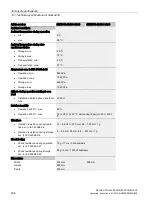
Страница 267: ...s 257 EMC directive 257 ESD guidelines 260 F Fault 180 Frequency fault 149 Frequency monitoring 149 Fuse replacement 188 Fuse types 188 fuses Checking 189 193 G GSD file download 104 GSDML file download 103 Guidelines ESD guidelines 260 H History 10 I Inrush current 133 L Line voltage compensation 139 Line voltage monitoring 147 Line voltage monitoring POM4320 Low voltage directive 257 M Manufactu...

Страница 268: ...s Control 132 Q Qualified personnel 9 R Recycling 203 Registered trademarks 11 S Safety information Changes to the devices 13 Circuit breaker 13 Connecting 13 Fuse replacement 14 Repairs 14 Working on the device 14 Scope of delivery 35 Shipping Note 33 Storage 33 Storage conditions 33 T Target group 9 Technical Support 262 Temperature monitoring 149 ...

Отзывы: