


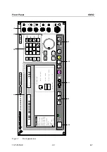


SMIQ
Front Panel
1125.5555.03
2.7
E-7
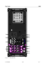
3
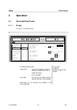
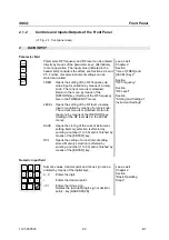
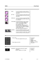
MENU/VARIATION
Rotary knob
The rotary knob moves the menu cursor over the
positions of a menu level to choose from or varies the
value of a parameter. The variation is either effected in
steps of one or in a step width that can be specified at will.
See as well
Chapter 2
Section "Basic
Operating Steps"
Section
"Sample Setting for
First Users"
4
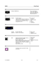
DATA
DATA
Input external data signal for digital mo-
dulation. Input resistance 1 k
Ω
or 50
Ω
,
Trigger threshold can be set from -2.5 to
+ 2.5V, max.
±
15 V, max. 40 mA.
Output* data signal with operating mode
internal. Level: TTL
See as well
Chapter 2,
Section
"Digital Modulation"
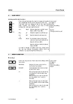
BIT
CLOCK
BIT
CLOCK
Input* external clock-pulse signal for
synchronization of external data signal.
Input resistance 1 k
Ω
or 50
Ω
,
Trigger threshold can be set from -2.5 to
+ 2.5 V, max.
±
15 V, max. 40 mA.
Output* clock-pulse signal with operating
mode internal. Level: TTL
SYMBOL
CLOCK
SYMBOL
CLOCK
Input* external clock signal for
synchronization of the external data
signal with polyvalent modulation types
with several bits per symbol.
Input resistance 1 k
Ω
or 50
Ω
,
Trigger threshold can be set from -2.5 to
+ 2.5V, max.
±
15 V, max. 40 mA.
Output* symbol clock signal with
operating mode internal. Level TTL
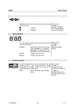
(BB-AM)
I
(BB-AM)
I
Input external modulation signal for I/Q
modulation and broadband-AM.
Output* I-signal with operating mode
internal.
Input/output resistance 50
Ω
.
Nominal voltage (I/Q): Us = 0.5 V
Nominal voltage (BB-AM): Us=0.25V
max. permissible overvoltage:
±
5V
Section
"Vector Modulation"
and
Section
"Broadband AM"


