


SMIQ
Enhanced Functions For Digital Standard 3GPP W-CDMA (FDD)
1125.5555.03
E-9
2.245
2.15.3.1.4
External Power Control
Two test constellations have to be distinguished in the test of Closed (Inner) Loop Power Control:
1. Test whether the DUT responds with the correct output power to received TPC bits (e.g. for testing
according to [1], 6.4.2.1). This can be carried out by using a data list adapted to the test condition as TPC
data source. The TPC pattern can be defined in the channel table (see previous section, “Menu
WCDMA/3GPP - Submenu BS Configuration“ or “Menu WCDMA/3GPP - Submenu MS Configuration“,
and also section 2.15.3.1.5).
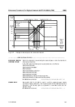
2. Test whether the DUT correctly performs the SIR (Signal to Interference Ratio) measurement and
inserts the corresponding bits into the TPC field of its transmit signal. Since the SMIQ has no
receive channel, the TPC control information has to be taken to the generator via another channel.
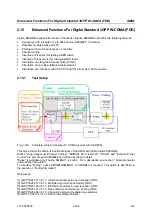
This is possible via "External Power Control".
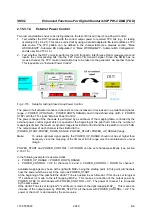
Fig. 2-170
Setup for testing Closed Loop Power Control
The power of all activated enhanced channels can be increased or decreased in a predefined dynamic
range (= POWER UP RANGE + POWER DOWN RANGE) and in the defined step width (= POWER
STEP) with the TTL signal “External Power Control“.
The power change of the channels is performed by a switchover of the mapping table, controlled by the
external power control signal which is queried at the beginning of the pilot field. Since the number of
mappings is limited, the maximum dynamic range is restricted to 30 dB and the step width to min. 0.25 dB.
The output power of each channel is thus limited to the
[POWER_START-POWER_DOWN_RANGE...POWEPOWER_UP_RANGE] range.
Note
:
To obtain optimum signal quality, the POWER_UP_RANGE should not be set higher than
necessary since the mapping of the I/Q level in this range must be maintained as a level
margin.
POWER_START and POWER_CONTROL = UP/DOWN can be set channel-specifically (see section
2.15.3.1.5).
In the following example it is assumed that
•
POWER_UP_RANGE = POWER_DOWN_RANGE
•
POWER_CONTROL = UP for channels 0, 2 and 3, POWER_CONTROL = DOWN for channel 1
Available mappings are shown at the right with MAP
M
being the starting point. In this point, all channels
have the power which was set in the menu as POWER_START.
At the beginning of the pilot field the LEVATT line is queried in each timeslot. If this line is set to logical
"0" switchover is made to the left mapping MAP
M-1
. This means a reduction of the output power by
POWER_STEP for all channels with POWER_CONTROL = UP . The power of channel 1 is increased
by the same value.
If the LEVATT line is set to logical "0" switchover is made to the right mapping MAP
M+1
. This means an
increase of the output power by POWER_STEP for all channels with POWER_CONTROL = UP. The
power of channel 1 is decreased by the same value.


