


Digital Modulation
SMIQ
1125.5555.03
E-9
2.100
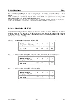
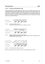
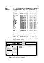
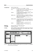
The following figure illustrates the effect of the envelope control signals.
BURST GATE
LEV ATT
RF OUT
Fig. 2-60
Signal waveforms during envelope control
Note:
Envelope control with digital input signals and edge shaping is only possible for symbol
rates of maximum 2.5 Msymb/s.
Envelope control is switched on in the menu via:
analog
POWER RAMP CONTROL - SOURCE - EXT ANALOG.
external digital POWER RAMP CONTROL - SOURCE - EXT DIGITAL.
internal digital POWER RAMP CONTROL - SOURCE - INT and SOURCE CONTROL STATE ON.
2.10.7 Clock
Signals
The symbol clock and the bit clock are generated in SMIQ by a clock synthesizer on the modulation
coder. All clock signals are synchronized to the 10 MHz reference of the unit. The symbol clock is
available at the SYMBOL CLOCK connector and the bit clock at the BIT CLOCK connector. If required,
the clock synthesizer in SMIQ can synchronize to an externally applied symbol or bit clock.
Only during an operation with external parallel data is synchronization to one symbol clock possible. This
symbol clock is applied via the PAR DATA interface. In all other cases, apply symbol and bit clock to the
corresponding BNC connector.
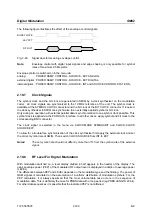
The clock signal is selected in the menu via CLOCK-MODE SYMBOL/BIT and CLOCK-CLOCK
SOURCE EXT.
To allow for a trouble-free synchronization of the clock synthesizer first apply the external clock and set
the correct symbol rate at SMIQ. Then switch CLOCK SOURCE from INT to EXT.
Notes:
The set symbol rate should not differ by more than 1% from the symbol rate of the external
signal.
2.10.8
RF Level For Digital Modulation
With modulation switched on, a level display divided in half appears in the header of the display. The
peak envelope power (PEP) of the modulated RF output level is displayed in addition to average power
(LEVEL).
The difference between PEP and LEVEL depends on the modulation type and the filtering. The power of
QAM signals is calculated on the assumption of a uniform distribution of modulation symbols. For the
PEP calculation, it is always assumed that the most unfavourable case occurs in the sequence of
modulation data. This is definitely the case for PRBS data with a long period (eg PRBS LENGTH 23 bit).
For other data sequences it is possible that the indicated PEP is not attained.


