


Fading Simulation
SMIQ
1125.5555.03
2.70
E-9
2.9 Fading
Simulation
By means of the option Fading Simulator SMIQB14, multipath fading signals with 6 independent
transmission paths can be generated.
Important:
The Fading Simulator can only be operated with the complex baseband signals
I and Q. Therefore, it is necessary to switch on either Vector Modulation or Digital
Modulation.
sin( t)
ω
cos( t)
ω
I
Q
ext
ext
RF OUT
IQ modulator
Baseband
fading
simulator
RF up/down converter
Modulation
coder
(SMIQB20)
I Q
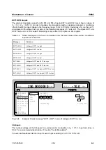
Fig. 2-36
Fading simulator in the SMIQ
The input signals for the fading simulator can either be applied to the modulation inputs I and Q or will
be generated in the SMIQ by the optional Modulation Coder (SMIQB20). The output signals of the fading
simulator will be passed to the IQ Modulator and then be mixed to the RF.
SMIQ can also be equipped with two Fading Simulators (SMIQB14 and SMIQB15). The second fading
option provides another 6 transmission paths.
If only one fading simulator is built in, output signals I and Q are available at the I FADED and Q FADED
connectors.
If two fading simulators are built in, the sum signal of the two fading options with 12 fading paths are
available at the I FADED and Q FADED connectors.
Note:
If option SMIQB17 (NDSIM) is fitted, the faded, noisy and distorted I/Q signals are present
at the I FADED and Q FADED connectors. If neither noise nor distortion is desired, set
DISTORTION in the NOISE/DIST menu to ON and select the predefined TEST list under
SELECT LIST to make sure that an output signal is present at the I FADED and Q FADED
connectors.
A selectable internal calibration of the fading simulator allows internal compensation of DC
offset voltages. The calibration routine should be called up after temperature changes of
more than 5 degree in menu UTILITIES-CALIB-VECTOR MOD.


