


Noise Generator and Distortion Simulator
SMIQ
1125.5555.03
2.388
E-9
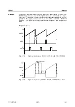
The two characteristics are formed by 2 data fields, the x-axis and the y-axis. 4 data fields therefore
have to be loaded for a new distortion characteristic. The minimum number of interpolation points that
can be entered for a characteristic is 5, the maximum number is 30. The limit values for the data fields
are as follows:
Input values (x-axis) of AM/AM conversion:
-100 dB to 0 dB
Output values (y-axis) of AM/AM conversion:
-100 dB to 0 dB
Input values (x-axis) of AM/PM conversion:
-100 dB to 0 dB
Output values (y axis) of AM/PM conversion:
-180° to +180°
2.24.3
Level Correction of the Distortion Simulator
The level correction influences the level if digital modulation is switched on (not with VECTOR MOD ON)
and the distortion simulator is active.
For the rms level set as LEVEL to appear at the RF output, the level control has to compensate for the
attenuation or gain of the distortion characteristic. For this purpose, level correction (-20 dB to 6 dB)
stored under the previously selected name is transmitted via IEC/IEEE-bus command. If this
characteristic is active, the output level is increased or decreased by the level-correction value. The
value by which the level is increased or decreased is indicated under LEVEL CORRECTION.
As the attenuation/gain of the distortion characteristic is dependent on the type of input signal being
dealt with, the level correction applies only to one particular type of digital modulation (modulation type,
filter type and filter parameters) and fading setting.
For the characteristic TWTA, for instance, which is supplied as standard, -3.12 dB is stored as level
correction. This value only applies to "WorldSpace Modulation" (QPSK, SQR-COS/0.4).
For the determination of level correction through measurement, the parameter is at first set to 0 dB via
IEC/IEEE bus. The desired type of digital modulation is then set, and the characteristic TEST (linear
characteristic supplied, LEVEL CORRECTION = 0 dB) activated, followed by the new characteristic. The
level difference of the two characteristics is measured at the RF output by means of an RF level meter.
The level correction for the new characteristic is then adjusted to the level difference measured via
IEC/IEEE bus. If the level difference is measured again, the result should be 0 dB
±
0.1 dB.
As theoretically the characteristic gain (negative level correction) cannot exceed the crest factor of the
modulation used, the warning "Warning 426 Absolute value of level correction > crest factor of Digital
Mod;" is displayed if the magnitude of the negative level correction exceeds the crest factor. The
correction is also restricted to the crest factor when the level is set, so LEVEL and PEP are identical.


