


67
<Functions of Linkage Menu>
● Select the function name
and return to the Linkage
menu by touching the
RTN
button or pushing the
Home/Exit
button.
<SensorTouch™>
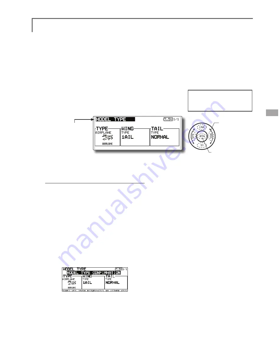
MODEL TYPE
This function selects the model type from among airplane, helicopter,
and glider.
(The display screen is an example. The screen
depends on the model type.)
Seven types of main wings and three types
of tail wings are available for airplanes. Eight
swash types are available for helicopters. Seven
types of main wings and three types of tail wings
are available for gliders. Functions and mixing
functions necessary for each model type are set in
advance at the factory.
Note: The Model Type function automatically selects
the appropriate output channels, control functions,
and mixing functions for the chosen model type.
When the Model Type Selection command is
accessed, all of the data in the active memory is
cleared (except the following swash type.) Be sure
that you don’t mind losing this data, or back it up to
another memory using the copying functions.
When you change the helicopter swash type
within the following each group, you can leave
the setting data other than the SWASH function. In
this case, confirmation screen appears. However,
it is initialized when you change the swash type
exceeding the group.
Model type selection
1. Use the touch sensor to move the cursor to
the item you want to change and then call
the selection screen by touching the RTN
button.
"TYPE": Model type
"WING " (airplane/glider): Wing type
"TAIL" (airplane/glider): Tail type
"SWASH" (helicopter): Swash type
2. Use the touch sensor to move the cursor to
the type you want to change and select the
type by touching the RTN button.
*When the model type was changed, the wing type, tail
type, or swash type selection screens sequentially appear
according to the model. Finally, the blinking confirmation
message "MODEL TYPE CONFIRMATION" appears.
3. Touch the RTN button to execute the
change. (Operate the touch sensor or S1
button to stop the change.)
● Select [MODEL TYPE] at the linkage menu and call
the setup screen shown below by touching the
RTN button.
*The model types which are displayed (which can be
selected) depend on the type of receiver used. See Servo
Connection by Model Type.
Swash type group A:
H-1, H-2, H-3, HR3, HN3, and HE3
Swash type group B:
H-4, H-4X
●Calling setup screen
Scrolling
● Moving cursor
● Selecting mode
Содержание FX-32
Страница 1: ...Instruction Manual FX 32 No F8078 ...
Страница 9: ...9 Introduction Notes ...


