87
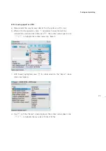
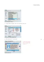
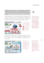
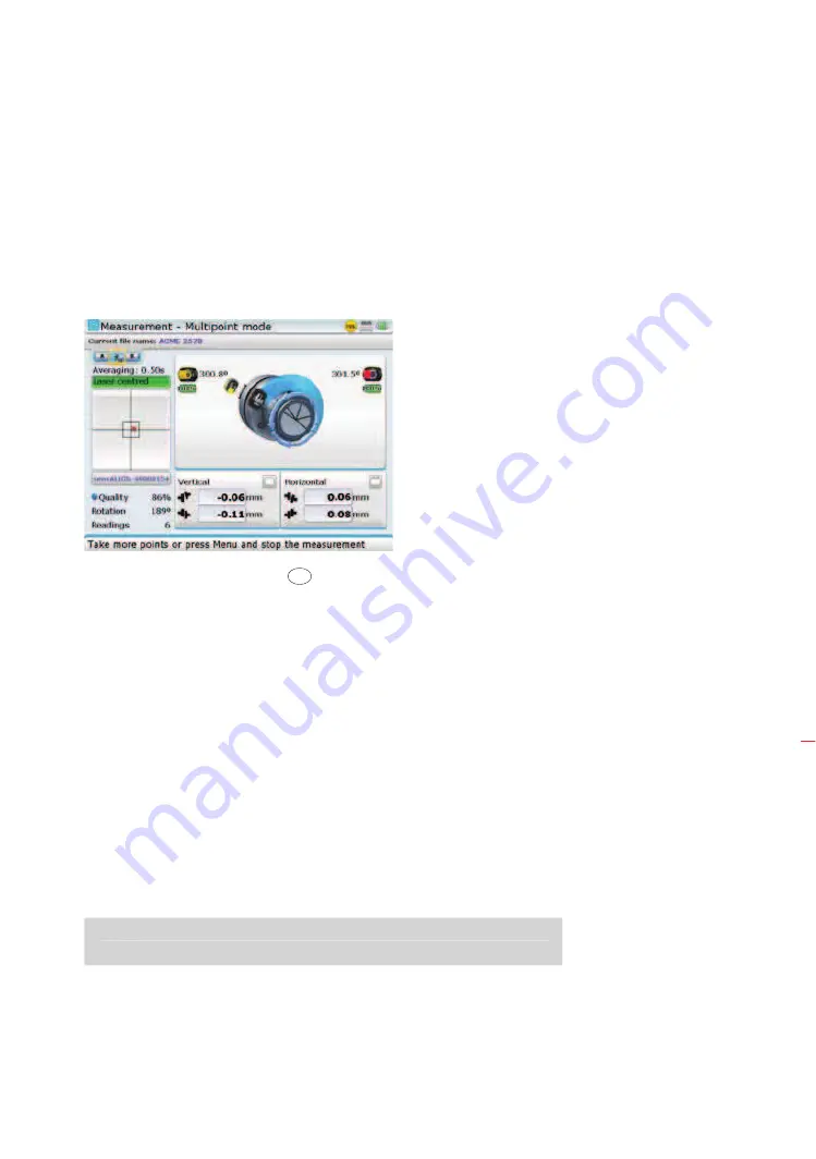
After centering the laser beam as described in section 4.10, press
e
to take the
first measurement point. Rotate shafts in their normal direction of operation from
one measurement position to the next. Press
e
to take measurement at each new
position. Measurements must be taken in at least three positions over at least 60° of
rotation, but more measurements over a wider angle is recommended.
After finishing measurement, press
RES
to view results.
5.1.3 Static measurement
This measurement mode is used for uncoupled shafts, nonrotatable shafts and vertical
foot-mounted or flange-mounted machines.
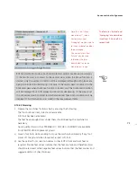
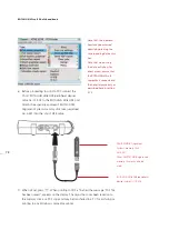
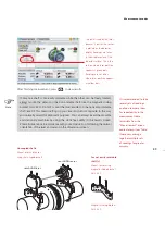
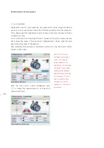
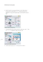
After centering the laser beam as described in chapter 4, turn the shaft to any of
the eight 45° positions (i.e. 12:00, 1:30, 3:00, 4:30, 6:00, 7:30, 9:00 or 10:30
o’clock position viewed from sensor towards laser). Position shaft as accurately as
possible using either an external inclinometer or protractor. Press
e
to take the first
measurement point.
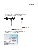
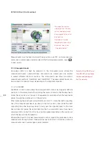
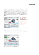
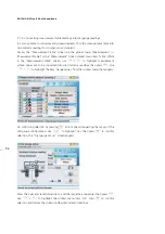
Rotate shaft to the next measurement position. Use the navigation keys to position
the displayed sensALIGN laser and sensor at an angular rotation corresponding to the
actual position of the components as mounted on the shafts.
Take next measurement point by pressing
e
.
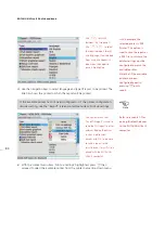
Note that after
e
has been pressed, the displayed sensALIGN laser and sensor move
to the next clock position on the display.
If shaft rotation restrictions hinder the taking of measurements at particular shaft
positions, bypass these using the navigation keys.
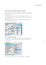
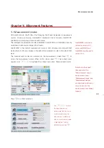
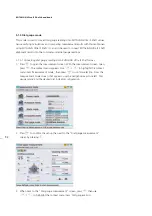
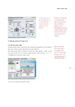
While in the
“Measurement mode”
screen you may also set-up
the averaging duration
and the measurement
factor.
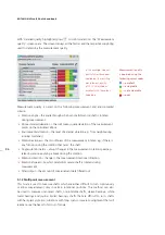
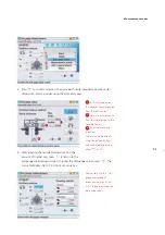
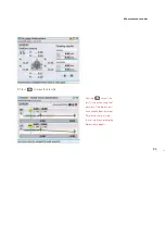
Coupling results are
displayed after a rotation
of at least 60°. If using
standard deviation (SD),
the value appears after
4 or more readings. For
best results take 5 or more
points. The more points
that are taken the more
points can be deleted in
the “Edit points” screen
to maximize accuracy. A
detailed description of
this utility appears under
‘Edit raw data’ in section
5.2.5.
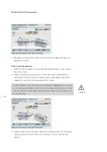
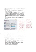
Note that after
e
has been pressed, the
displayed sensALIGN
laser and sensor move to
the next clock position
on the display. Use
the navigation keys to
position both laser and
sensor manually.
Note
If shaft rotation restrictions hinder the taking of measurements at particular shaft
positions, bypass these using the navigation keys.
Measurement modes
Содержание ROTALIGN Ultra iS
Страница 1: ...ROTALIGN Ultra iS Operating handbook Shaft alignment...
Страница 11: ...ROTALIGN Ultra iS Shaft handbook 10 This page intentionally left blank...
Страница 56: ...55 Horizontal shaft alignment 1 2 4 5 6...
Страница 123: ...ROTALIGN Ultra iS Shaft handbook 122 Page intentionally left blank...
Страница 141: ...ROTALIGN Ultra iS Shaft handbook 140 This page intentionally left blank...
Страница 177: ...ROTALIGN Ultra iS Shaft handbook 176 Page intentionally left blank...
Страница 207: ...ROTALIGN Ultra iS Shaft handbook 206 Page intentionally left blank...
Страница 213: ...ROTALIGN Ultra iS Shaft handbook 212 Declaration of conformity...
Страница 219: ...ROTALIGN Ultra iS Shaft handbook 218...

