111
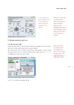
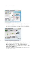
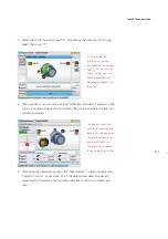
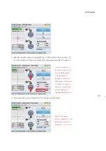
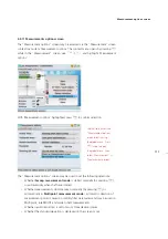
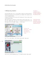
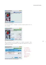
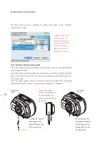
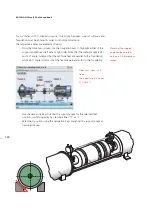
3. Rotate the shafts through at least 90°, indicated by the rotational arc turning
green, then press
e
.
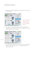
4. After completion, an instruction on any further laser adjustment appears on the
screen, including a blue dot which indicates the position to where the laser dot
should be adjusted.
5. After using the intelli laser position, the “Measurement” screen submenu item
‘Position to center’ is now active. This is the default laser beam adjustment
procedure but it becomes inactive when intelli laser position is activated and
used.
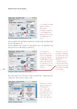
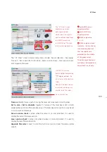
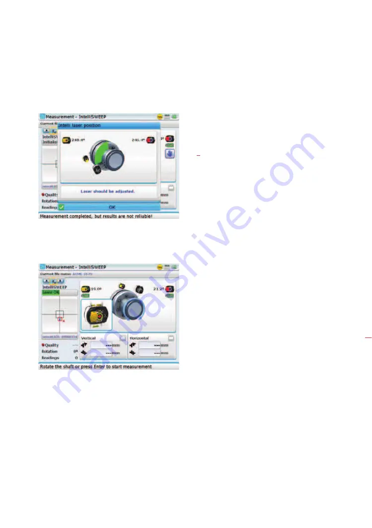
In this example, the
rotational arc is green
indicating that the rotation
is > 90°. For this case, the
advice to adjust the laser
before proceeding with
measurement appears on
the screen.
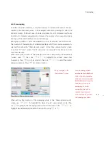
The blue dot shows the
position to where the laser
beam dot is to be adjusted.
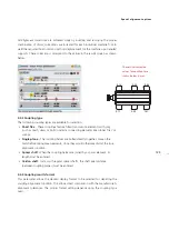
The laser beam dot is no
longer adjusted to the
center, but use is made of
the entire detector surface.
Intelli laser position
Содержание ROTALIGN Ultra iS
Страница 1: ...ROTALIGN Ultra iS Operating handbook Shaft alignment...
Страница 11: ...ROTALIGN Ultra iS Shaft handbook 10 This page intentionally left blank...
Страница 56: ...55 Horizontal shaft alignment 1 2 4 5 6...
Страница 123: ...ROTALIGN Ultra iS Shaft handbook 122 Page intentionally left blank...
Страница 141: ...ROTALIGN Ultra iS Shaft handbook 140 This page intentionally left blank...
Страница 177: ...ROTALIGN Ultra iS Shaft handbook 176 Page intentionally left blank...
Страница 207: ...ROTALIGN Ultra iS Shaft handbook 206 Page intentionally left blank...
Страница 213: ...ROTALIGN Ultra iS Shaft handbook 212 Declaration of conformity...
Страница 219: ...ROTALIGN Ultra iS Shaft handbook 218...

