167
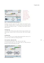
6.4.2 Flange geometry and dimensions
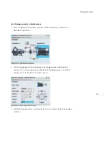
1. After configuring the machines, proceed to enter all necessary dimensions as
described in section 4.7.
2. Edit the flange geometry by highlighting the flange-mounted machine then
pressing
e
. A hint requesting the definition of the flange appears. Confirm by
pressing
e
. The flange editing screen appears.
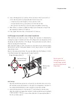
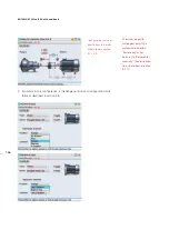
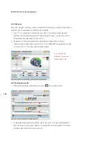
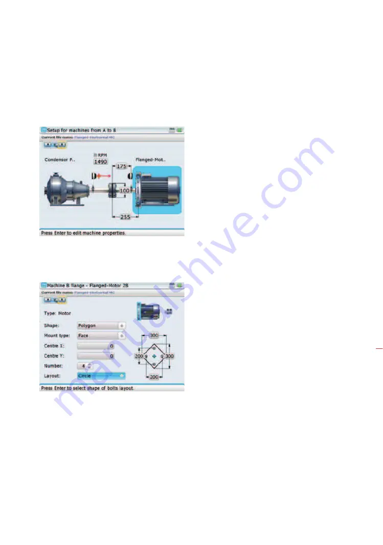
c) Edit the flange geometry as described in section 6.3.3 previously (Set-up flanged
machines).
Flanged machines
Содержание ROTALIGN Ultra iS
Страница 1: ...ROTALIGN Ultra iS Operating handbook Shaft alignment...
Страница 11: ...ROTALIGN Ultra iS Shaft handbook 10 This page intentionally left blank...
Страница 56: ...55 Horizontal shaft alignment 1 2 4 5 6...
Страница 123: ...ROTALIGN Ultra iS Shaft handbook 122 Page intentionally left blank...
Страница 141: ...ROTALIGN Ultra iS Shaft handbook 140 This page intentionally left blank...
Страница 177: ...ROTALIGN Ultra iS Shaft handbook 176 Page intentionally left blank...
Страница 207: ...ROTALIGN Ultra iS Shaft handbook 206 Page intentionally left blank...
Страница 213: ...ROTALIGN Ultra iS Shaft handbook 212 Declaration of conformity...
Страница 219: ...ROTALIGN Ultra iS Shaft handbook 218...

