ROTALIGN Ultra iS Shaft handbook
60
4.12a Taking measurements using the sensALIGN sensor
and laser cable
If necessary, measurement data from sensALIGN sensor may be transferred to
ROTALIGN Ultra iS computer using the sensALIGN sensor and laser cable ALI 4.921-2.
Such cases may arise due to low sensor battery capacity or when measurement is
carried out with the sensor rechargeable battery dismounted.
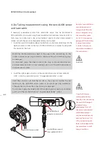
1. Insert the quick fit straight-ended sensALIGN sensor and laser cable plug into the
eight-pin sensor socket on the top of ROTALIGN Ultra iS computer housing with
the red dot at the front.
Match the double-sided arrow head on the plug to the red marking on the
socket to ensure proper plug orientation; otherwise the pins inside the plug may
be damaged.
To disconnect, grasp the ribbed collar of the plug on the sensALIGN sensor
and laser cable (ALI 4.921-2) and carefully pull it out of the ROTALIGN Ultra iS
computer sensor socket.
2. Insert the right-angle connector on the sensALIGN sensor and laser cable ALI
4.921-2 into the sensALIGN sensor “charger/adapter/cable” socket.
Insert the connector such that the red dot on the connector matches the red
marking on the sensALIGN sensor socket to ensure proper plug orientation;
otherwise the pins inside the connector may be damaged.
To disconnect, grasp the ribbed collar of the right-angled connector and carefully
pull it out of the sensALIGN sensor “charger/adapter/cable” socket.
Note that sensALIGN laser
may also be powered
through the ROTALIGN
Ultra iS computer using
the sensor/laser cable
ALI 4.921-2. Connection
between ROTALIGN Ultra
iS computer and laser
is similar to the sensor
connection described on
the main column.
CAUTION
Match the double-sided arrow head on the plug to the red marking on the
socket to ensure proper plug orientation; otherwise the pins inside the plug may
be damaged.
To disconnect, grasp the ribbed collar of the plug on the sensALIGN sensor
and laser cable (ALI 4.921-2) and carefully pull it out of the ROTALIGN Ultra iS
computer sensor socket.
CAUTION
Insert the connector such that the red dot on the connector matches the red
marking on the sensALIGN sensor socket to ensure proper plug orientation;
otherwise the pins inside the connector may be damaged.
To disconnect, grasp the ribbed collar of the right-angled connector and carefully
pull it out of the sensALIGN sensor “charger/adapter/cable” socket.
If sensALIGN sensor
rechargeable battery
capacity is low, connecting
the sensALIGN charger/
adapter during
measurement cuts off
the sensor measurement
mode. Measurement
may be resumed only by
pressing the sensor ‘On/
Off’ push button briefly.
Refer to the appendix for
the sensor/laser ‘on/off/
charge’ workflow.
OP
EN
sensALIGN sensor and
laser cable ALI 4.921-2
sensALIGN sensor socket
ROTALIGN Ultra iS
computer sensor socket
Содержание ROTALIGN Ultra iS
Страница 1: ...ROTALIGN Ultra iS Operating handbook Shaft alignment...
Страница 11: ...ROTALIGN Ultra iS Shaft handbook 10 This page intentionally left blank...
Страница 56: ...55 Horizontal shaft alignment 1 2 4 5 6...
Страница 123: ...ROTALIGN Ultra iS Shaft handbook 122 Page intentionally left blank...
Страница 141: ...ROTALIGN Ultra iS Shaft handbook 140 This page intentionally left blank...
Страница 177: ...ROTALIGN Ultra iS Shaft handbook 176 Page intentionally left blank...
Страница 207: ...ROTALIGN Ultra iS Shaft handbook 206 Page intentionally left blank...
Страница 213: ...ROTALIGN Ultra iS Shaft handbook 212 Declaration of conformity...
Страница 219: ...ROTALIGN Ultra iS Shaft handbook 218...

