ROTALIGN
®
Ultra iS Shaft handbook
156
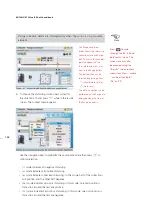
6.3.2 Marking measurement positions
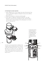
1. Mark a reference position on the coupling housing close to the shaft and in line
with a convenient external reference or flange bolt. Likewise, mark a reference
point on the shaft.
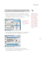
2. Measure the circumference of the shaft and divide by eight.
3. Use this distance to make seven more evenly-spaced marks on the shaft
beginning at your chosen start point. Number the points counterclockwise as
seen from sensor to laser, beginning with 0 first, followed by 1:30, 3:00,4:30,
6:00, 7:30, 9:00 and 10:30.
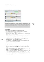
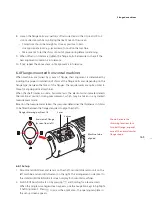
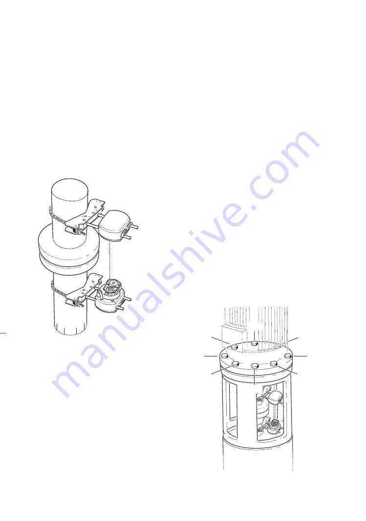
For circular housings, measure the circumference of the
coupling housing and divide by eight. Use this distance
to make eight evenly-spaced marks on the housing
beginning at your chosen start point. Number the
points clockwise looking down onto the shaft with 0
as the first, followed by 1:30, 3:00,4:30, 6:00, 7:30,
9:00 and 10:30.
0:00
1:30
3:00
4:30
0:00
6:00
10:30
7:30
9:00
1:30
4:30
3:00
Evenly-spaced marks are
made on the bearing
housing beginning with
0 as the reference and
numbered clockwise
looking down onto the
shaft.
Содержание ROTALIGN Ultra iS
Страница 1: ...ROTALIGN Ultra iS Operating handbook Shaft alignment...
Страница 11: ...ROTALIGN Ultra iS Shaft handbook 10 This page intentionally left blank...
Страница 56: ...55 Horizontal shaft alignment 1 2 4 5 6...
Страница 123: ...ROTALIGN Ultra iS Shaft handbook 122 Page intentionally left blank...
Страница 141: ...ROTALIGN Ultra iS Shaft handbook 140 This page intentionally left blank...
Страница 177: ...ROTALIGN Ultra iS Shaft handbook 176 Page intentionally left blank...
Страница 207: ...ROTALIGN Ultra iS Shaft handbook 206 Page intentionally left blank...
Страница 213: ...ROTALIGN Ultra iS Shaft handbook 212 Declaration of conformity...
Страница 219: ...ROTALIGN Ultra iS Shaft handbook 218...

