105
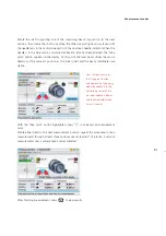
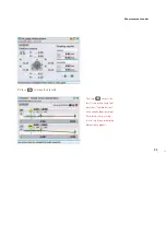
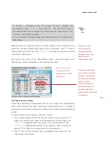
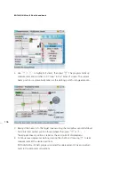
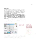
The ‘view mode’ allows raw data to be examined from three different views. The three
views are: ellipse and corresponding points, plane points and broken ellipse. Use the
navigation keys to highlight the desired view then confirm selection by pressing
e
.
In the “Ellipse and points” view, the width of the ellipse along the X axis gives an
indication of shaft angularity, and its height (on the Y axis) indicates shaft offset.
When shafts are perfectly aligned, the ellipse is reduced to a single point.
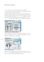
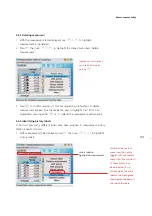
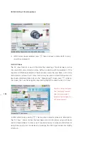
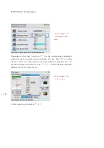
‘Toggle point’
is used to deactivate any selected measurement point. Use
f
/
g
to highlight ‘Toggle point’, then press
e
to deactivate the selected point. This point
may be reactivated by the same procedure. The ‘deactivated’ measurement position
can be remeasured in the ‘Multipoint’, ‘Pass’ and ‘Static’ measurement modes. If
several ‘active’ points result for the same position, they will be averaged together.
‘Max point’
is used to highlight the measurement point with the maximum deviation
from the calculated ellipse.
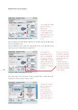
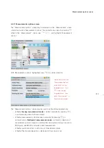
Selecting
‘Sensor on’
shows the current beam position on the screen. With this
function, repeatability can be checked by following the path of the beam as the shafts
are turned through the measurement positions again. The beam should move along
the curve of the ellipse without appreciable deviation.
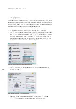
5.2.6 Extending the measurement range
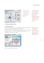
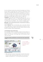
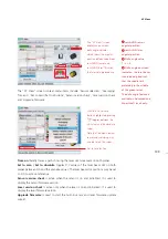
Gross misalignment of shafts or small angular misalignment over large distances can
cause the laser beam to miss the detector surface during measurement. When this
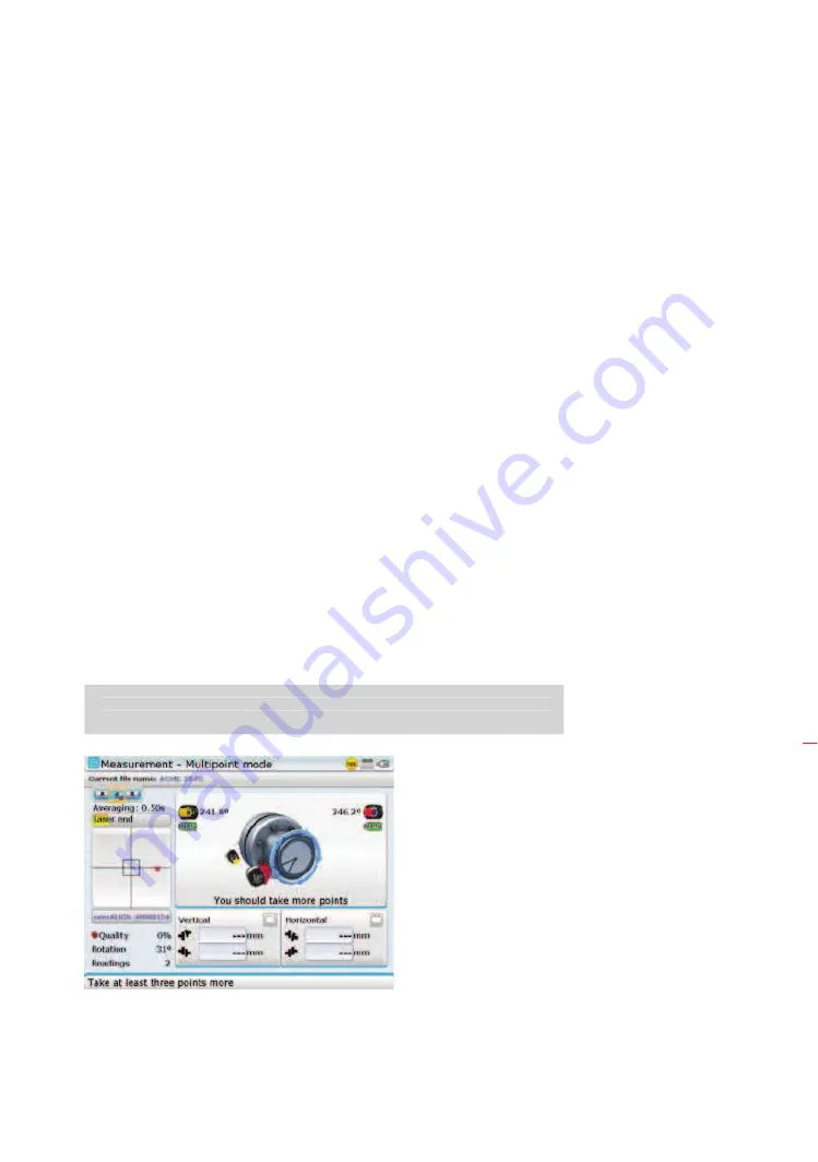
happens, ‘Laser end’ appears on the display screen and the instrument’s ‘Extend’
function can be used.
The ‘Extend’ option is available only in ‘Multipoint’ and ‘Static’ measurement
modes.
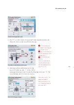
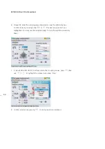
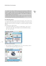
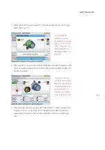
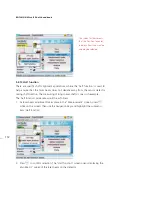
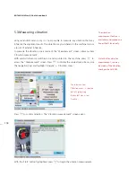
1. When measuring and ‘Laser end’ message appears, rotate the shafts backwards
until the laser beam reenters the measurement range. The message ‘Laser OK’
reappears on the display. Press
q
. The context menu shown next appears.
Note
The ‘Extend’ option is available only in ‘Multipoint’ and ‘Static’ measurement
modes.
‘Laser end’ is displayed
when the laser falls outside
of the linearized range of
the detector.
Extend
Содержание ROTALIGN Ultra iS
Страница 1: ...ROTALIGN Ultra iS Operating handbook Shaft alignment...
Страница 11: ...ROTALIGN Ultra iS Shaft handbook 10 This page intentionally left blank...
Страница 56: ...55 Horizontal shaft alignment 1 2 4 5 6...
Страница 123: ...ROTALIGN Ultra iS Shaft handbook 122 Page intentionally left blank...
Страница 141: ...ROTALIGN Ultra iS Shaft handbook 140 This page intentionally left blank...
Страница 177: ...ROTALIGN Ultra iS Shaft handbook 176 Page intentionally left blank...
Страница 207: ...ROTALIGN Ultra iS Shaft handbook 206 Page intentionally left blank...
Страница 213: ...ROTALIGN Ultra iS Shaft handbook 212 Declaration of conformity...
Страница 219: ...ROTALIGN Ultra iS Shaft handbook 218...

