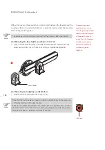
149
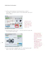
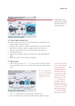
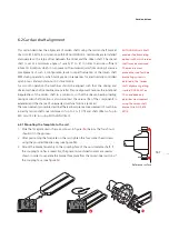
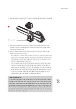
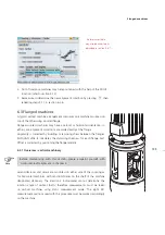
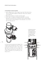
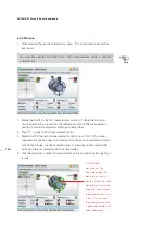
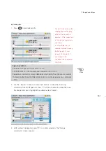
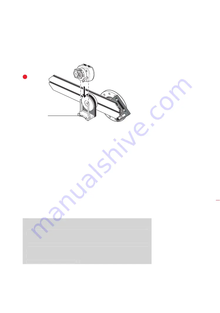
2. Slide the laser onto the posts until it rests on the distance plate (refer to figure
3b
).
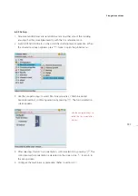
3. Mark a set of target crosshairs on the shaft rotation centerline of the other
machine coupling (if the flange has a center hole, a temporary target surface
may be affixed to the hole).
4. Switch sensALIGN laser on then adjust the beam to strike the center of the
target on the opposite coupling:
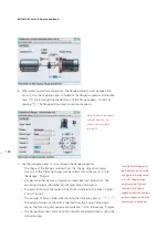
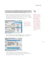
› The objective is to adjust the laser beam such that it is roughly colinear to the
rotational axis of the laser holder assembly; this will make it possible to make
fine adjustments to the laser holder assembly’s position afterwards, without
having to realign the laser beam itself.
› The two yellow beam position thumbwheels are used to adjust the angular
position of the laser beam. By rotating the laser assembly holder, the laser
beam traces an ‘approximate’ circle. If the ‘approximate’ circle is a single dot
at the center of the target, then the laser beam has been adjusted correctly.
If that is not the case, repeat the laser beam adjustment process until the
‘approximate’ circle corresponds to a single dot position.
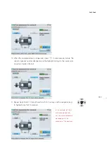
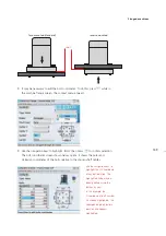
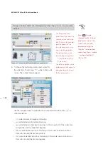
Laser adjustment tip
If the beam describes a circle rather than a dot at the target when rotating
the laser holder assembly, then note how big the circle is and use the yellow
adjustment thumbwheels to move the laser beam back by half the distance it has
moved when rotating the laser holder assembly 180° from its start position. Do
this both vertically and horizontally. When correctly adjusted, you should be able
to rotate the laser holder assembly a full 360° without the laser dot moving from
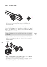
the target center (refer to figure
3c
).
Distance plate
Note
Laser adjustment tip
If the beam describes a circle rather than a dot at the target when rotating
the laser holder assembly, then note how big the circle is and use the yellow
adjustment thumbwheels to move the laser beam back by half the distance it has
moved when rotating the laser holder assembly 180° from its start position. Do
this both vertically and horizontally. When correctly adjusted, you should be able
to rotate the laser holder assembly a full 360° without the laser dot moving from
the target center (refer to figure
3c
).
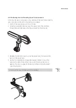
Cardan drives
3b
Содержание ROTALIGN Ultra iS
Страница 1: ...ROTALIGN Ultra iS Operating handbook Shaft alignment...
Страница 11: ...ROTALIGN Ultra iS Shaft handbook 10 This page intentionally left blank...
Страница 56: ...55 Horizontal shaft alignment 1 2 4 5 6...
Страница 123: ...ROTALIGN Ultra iS Shaft handbook 122 Page intentionally left blank...
Страница 141: ...ROTALIGN Ultra iS Shaft handbook 140 This page intentionally left blank...
Страница 177: ...ROTALIGN Ultra iS Shaft handbook 176 Page intentionally left blank...
Страница 207: ...ROTALIGN Ultra iS Shaft handbook 206 Page intentionally left blank...
Страница 213: ...ROTALIGN Ultra iS Shaft handbook 212 Declaration of conformity...
Страница 219: ...ROTALIGN Ultra iS Shaft handbook 218...

