Graphics
4-12
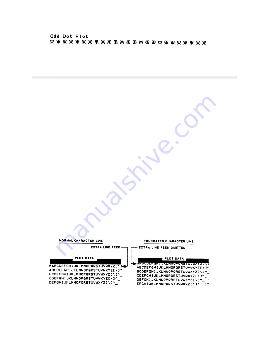
Figure 4-11. Sample Odd Dot Plot
Combining Graphics and Text
P6000L/P6200L Series printers are capable of combining graphics and characters (text) on the
same page in two ways: using Bit Image graphics or P-Series Plot mode to produce characters
as well as graphics and using a combination of print mode/graphics.
Any character or symbol can be created in the Plot mode or with Bit Image graphics simply by
addressing and plotting the appropriate dot positions. In this way, both graphics and text can be
produced on the same line in a single printing pass. However, Print mode is a faster, more effiĆ
cient method of producing characters.
Either Bit Image or Plot mode graphics can be mixed with text within the page on a line by line
basis. Each line of graphics data must include a graphics control code or the printer will autoĆ
matically default to the print mode. Using Bit Image graphics, it is possible to use the print
mode to produce text on one print pass followed by a print pass to produce graphics on the
same line; however, text characters can be affected by the Bit Image data when combined on
the same line.
When returning to the print mode from graphics, an extra line feed should be included in the
data stream to maintain proper line registration throughout the page. If the extra line feed is
not included, the first character line after the graphics data may be truncated as shown in
Figure 4-12.
The MODIFIED PLOT SELECT configuration option, as shown on the Control Panel Switch
Function Diagram, sheet 6 of 12 on page 3-22, will affect the translation from graphics to
print mode. MODIFIED PLOT DISABLED places the next line of text on the page as if the
current line spacing had been followed while plotting. MODIFIED PLOT ENABLED places
the next line of text on the dot row following the last dot row of plotting.
Figure 4-12. Truncated Character Line
Содержание P6000L
Страница 1: ...P600L P6200L Line Printers User s Reference Manual R...
Страница 2: ......
Страница 3: ...P6000L P6200L Line Printers User s Reference Manual R P N 140576 001 Rev C...
Страница 20: ...Overview 1 6...
Страница 23: ...2 3 Operation Figure 2 1 Power Switch Floor Cabinet Model Figure 2 2 Power Switch Pedestal Model...
Страница 28: ...Operation 2 8 Figure 2 4 Paper Adjustment Controls Floor Cabinet Model...
Страница 34: ...Operation 2 14 Figure 2 10 Loading Paper...
Страница 51: ...3 7 Configuration Figure 3 1 Sample Configuration Printout...
Страница 56: ...Configuration 3 12 Figure 3 4 PCBA Removal Pedestal Model Printer...
Страница 100: ...Vertical Format Units 5 16...
Страница 167: ...7 9 Interfaces Figure 7 1 Alternate Terminating Resistor Location Floor Cabinet Model...
Страница 169: ...7 11 Interfaces Figure 7 2 Alternate Terminating Resistor Location Pedestal Model...
Страница 190: ...RibbonMinder 9 14...
Страница 200: ...Installation 10 10 Figure 10 9 Side Shock Mount Restraint Screw Removal Floor Cabinet Model...
Страница 202: ...Installation 10 12 Figure 10 10 Pedestal Legs Installation Pedestal Model...
Страница 203: ...10 13 Installation Figure 10 11 Rubber Feet Removal Pedestal Model Figure 10 12 Pedestal Mounting Pedestal Model...
Страница 206: ...Installation 10 16 Figure 10 14 Shipping Restraint Removal Pedestal Model...
Страница 208: ...Installation 10 18 Figure 10 16 Cable Connections Pedestal Model...
Страница 210: ...Installation 10 20...
Страница 212: ...Appendix A 2...
Страница 213: ...B 1 Appendix APPENDIX B Serial Emulation Mode Character Set 1 80 9F Control Codes...
Страница 214: ...Appendix B 2 Serial Emulation Mode Character Set 2 80 9f Printable Symbols...
Страница 215: ...B 3 Appendix P Series Mode Character Set 1 80 9f Control Codes...
Страница 216: ...Appendix B 4 P Series Mode Character Set 2 80 9f Printable Symbols...
Страница 217: ...B 5 Appendix International Characters...
Страница 218: ...Appendix B 6...
Страница 232: ...P6000L P6200L User s Reference Manual Index 6...
Страница 233: ......


