38
Setup Procedure
Section 3-1
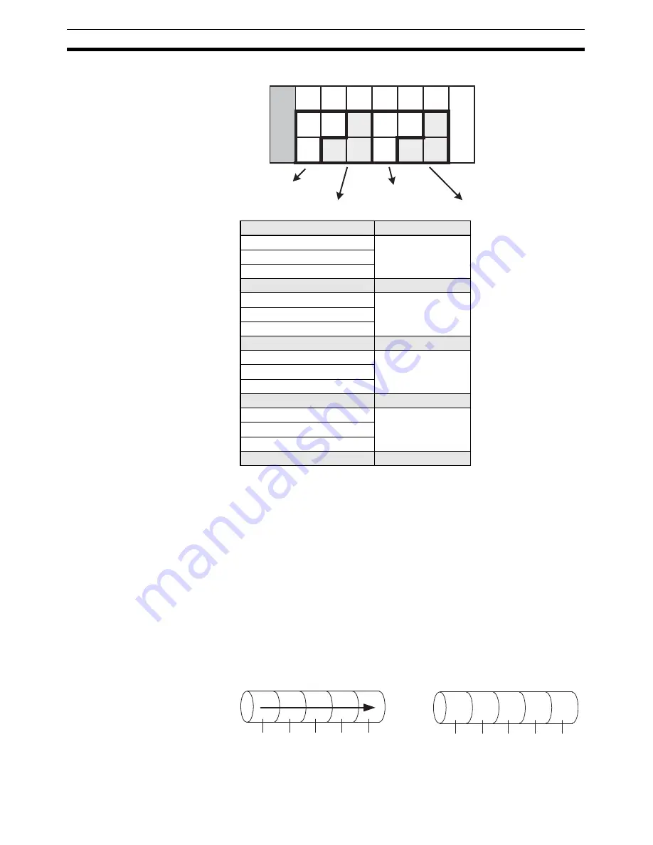
Note (a) The HFU can control up to 64 channels, but when the maximum
number of enabled channels is a number other than 4, 8, 16, or
32 channels, non-usable channels result as shown in this exam-
ple. This limits the number of controllable channels and connect-
able Units. Refer to Maximum Number of Connectable Units on
page 28 for details.
(b) If the maximum number of enabled channels is changed in the
configuration, the number of channels allocated for each group
and the initial channel for each group may change.
5.
Arrange the Sensors.
Arrange the sensors sequentially to maximize the control performance
within gradient temperature control groups.
Connection Example with Control Object Heaters in a Line
HFU channels
Groups
1
1
2
3
4
Not usable
5
2
6
7
8
Not usable
9
3
10
11
12
Not usable
13
4
14
15
16
Not usable
H
F
U
E
D
U
0 1 2
3
4
5
6
TC2
CH1
CH2
TC2 TC2 TC2 TC2 TC2
CH3 CH6 CH9 CH11 CH14
CH5 CH7 CH10 CH13 CH15
Group 1 (gradient)
Group 2 (gradient)
Group 3 (gradient)
Group 4 (2-PID control)
CH1 CH2 CH3 CH4 CH5
CH1 CH3 CH5 CH4 CH2
Good example
Bad example
Содержание EJ1G
Страница 1: ...USER S MANUAL Modular Temperature Controllers for Gradient Temperature Control EJ1G Cat No H143 E1 01 ...
Страница 3: ...iv ...
Страница 17: ...xviii ...
Страница 21: ...xxii ...
Страница 53: ...32 Unit Configuration Examples Section 2 4 ...
Страница 69: ...48 Changing SPs During Operation Section 3 3 ...
Страница 81: ...60 Other Functions Section 4 5 ...
Страница 145: ...124 Other HFU Functions Section 5 7 ...
Страница 167: ...146 Detailed Description of Services Section 6 4 ...
Страница 189: ...168 Determining the Error from the Current Situation for Heater Burnout Alarm Errors Section 7 8 ...
Страница 229: ...208 Parameters That Can Be Allocated for Programless Communications Appendix ...
Страница 237: ......


