Page 72
Negative Limit Switch
17
Figure 11: Homing to the negative limit switch
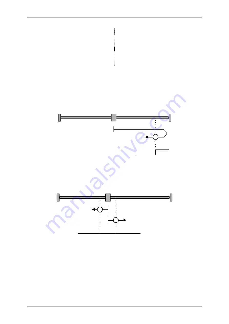
Method 18: Homing to the positive limit switch
If this method is used, the drive moves in the positive direction at search speed until it reaches the
positive limit switch. In Figure 12 this is represented by the rising edge. Then the drives moves back at
crawl speed and tries to find the exact position of the limit switch. The zero position refers the falling
edge of the positive limit switch.
Positive Limit Switch
18
Figure 12: Homing to the positive limit switch
Methods 33 and 34: Homing to the index pulse
In the case of method 33 and method 34 the direction of the homing run is negative or positive. The
zero position refers to the first index pulse of the angle encoder in search direction.
Index Pulse
33
34
Figure 13: Homing run referred only to the index pulse
Method -1: Negative stop with index pulse evaluation
If this method is used, the drive moves in the negative direction until is reaches the stop. The
DUET_FL servo positioning controller needs at least 1 second to recognize the stop. The mechanical
design of the stop must be such that it cannot be damaged at the parameterized maximum current.
The zero position refers the first index pulse of the angle encoder in the positive direction from the
stop.
User Manual DUET_FL „DUET_FL 48/10“
Version 1.1 Motor Power Company
Содержание DUET_FL 48/10
Страница 3: ...ber dieses Handbuch Page 3...
Страница 4: ...Page 4 User Manual DUET_FL DUET_FL 48 10 Version 1 1 Motor Power Company...
Страница 12: ...Page 12 List of Figures User Manual DUET_FL DUET_FL 48 10 Version 1 1 Motor Power Company...
Страница 15: ...Page 15 List of Tables User Manual DUET_FL DUET_FL 48 10 Version 1 1 Motor Power Company...
Страница 76: ...Page 76 User Manual DUET_FL DUET_FL 48 10 Version 1 1 Motor Power Company...
Страница 196: ...Page 196 User Manual DUET_FL DUET_FL 48 10 Version 1 1 Motor Power Company...


