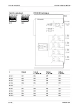
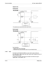
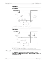
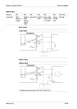
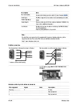
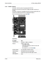
Mode 1: Continuous data output (follow), no DATA_IN
Continuous output of consistent data, provided continuously without request, e.g., for
remote display.
The driver modules are always "enabled"; PIN 25 is the output.
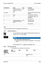
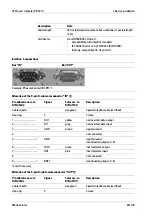
Mode 2: Data output on external request DATA_IN (hold)
Output of consistent data in "frozen" state upon request, otherwise provided conti-
nuously.
The last output value remains frozen (hold) for as long as DATA_IN is active.
The driver modules are always "enabled"; PIN 25 (DATA_IN) is data-hold, level S101-3,
polarity S101-4
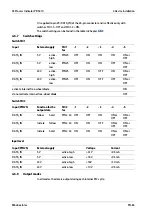
Note:
The internal data transfer (data modification) on the output memory may occur at the
same time that the external request signal changes from "data hold" to "data valid." This
means that the requested device still has to wait 100 µs until the data is considered
valid.
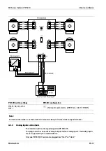
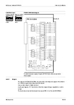
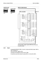
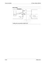
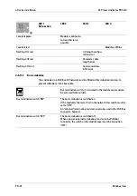
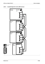
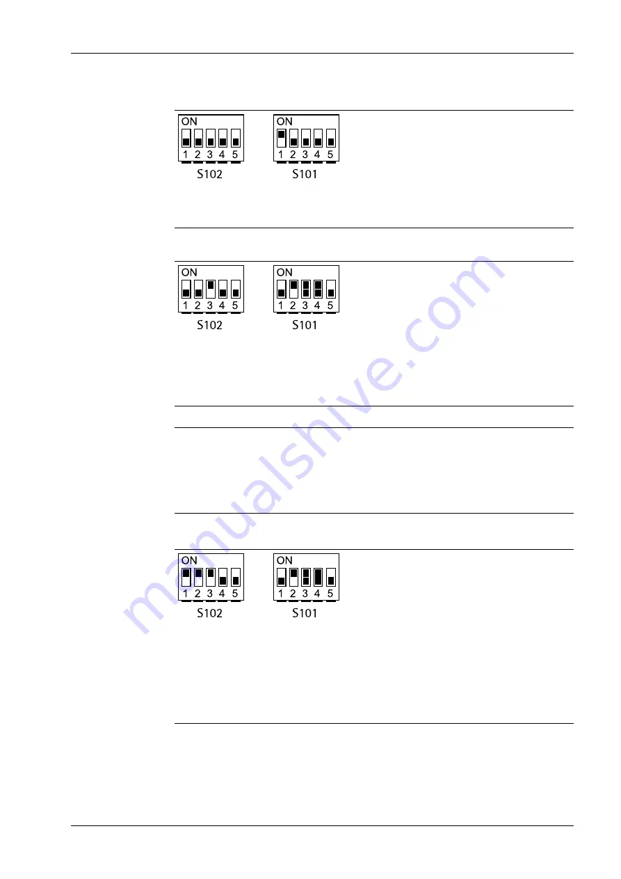
Mode 3: Parallel BUS system (tristate), external request DATA_IN (hold)
Parallel switching of n BCD cards, controlled via DATA_IN (tristate/hold) input.
Output of consistent data in "frozen" state upon request, otherwise "tristate" (highly re-
sistant).
-
The last output value remains frozen (hold) for as long as DATA_IN is active.
-
The driver modules are only "enabled" (not tristate) when DATA_IN (hold) is active
-
PIN 25 (DATA_IN) is data-hold, level S101-3, polarity S101-4
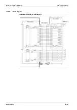
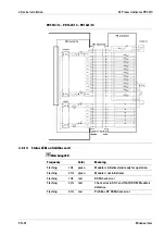
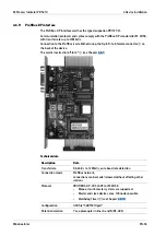
4 Device installation
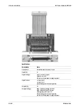
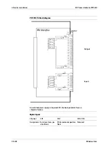
X3 Process Indicator PR 5410
EN-85
Minebea Intec


