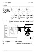
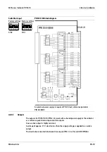
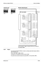
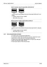
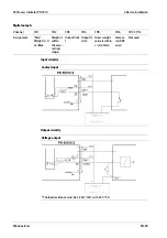
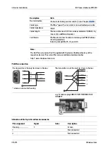
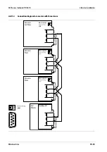

It is applied to pin 25 (DATA_IN) of the 26-pin connector and is effective only with
switches S101-1 = OFF and S101-2 = ON.
The switch settings can be found in the table in Chapter
4.6.7
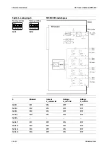
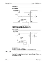
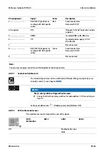
Switch settings
Switch S101
Input
External supply
S101
for
-1
-2
-3
-4
-5
DATA_IN
5 V
active-
high
PIN 25
OFF
ON
ON
ON
ON or
OFF
DATA_IN
5 V
active-
low
PIN 25
OFF
ON
ON
OFF
ON or
OFF
DATA_IN
24 V
active-
high
PIN 25
OFF
ON
OFF
ON
ON or
OFF
DATA_IN
24 V
active-
low
PIN 25
OFF
ON
OFF
OFF
ON or
OFF
activate internal free-wheel diode
ON
do not activate internal free-wheel diode
OFF
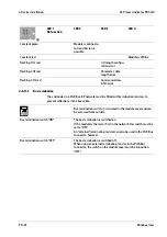
Switch S102
Input (PIN 25)
Function for the
output data
S102
for
-1
-2
-3
-4
-5
DATA_IN
follow
hold
PIN 2
24 OFF
OFF
ON
ON or
OFF
ON or
OFF
DATA_IN
tristate
follow
PIN 2
24 ON
ON
OFF
ON or
OFF
ON or
OFF
DATA_IN
tristate
hold
PIN 2
24 ON
ON
ON
ON or
OFF
ON or
OFF
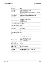
Input level
Input (PIN 25)
External supply
Voltage
Current
DATA_IN
5 V
active-high
>3.1 V
>0.5 mA
DATA_IN
5 V
active-low
<1.5 V
<0.3 mA
DATA_IN
24 V
active-high
>16 V
>1.0 mA
DATA_IN
24 V
active-low
<10 V
<0.5 mA
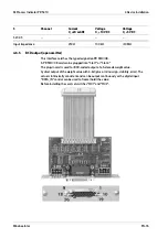
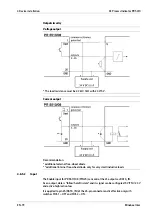
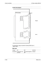
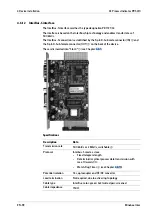
4.6.8
Output modes
In all modes, the data is output during each internal PLC cycle.
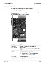
X3 Process Indicator PR 5410
4 Device installation
Minebea Intec
EN-84


