Chapter
3
Advanced Tool Tutorials
3-46
Getting Started with Visionscape GigE Cameras
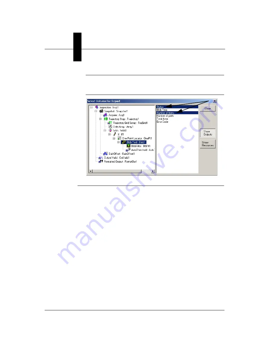
Note:
Blob Tool is in the One Point Locator. Once selected in the
Trajectory Step, the results are automatically enabled in the
Inspection Step results list.
FIGURE 3–34.
Select Datums for Report
15.
Highlight Trajectory Grid Setup in the Step Tree (left pane).
FrontRunner™ displays the Trajectory Grid Setup properties page.
The Trajectory Grid Setup step tells the system the locations of the
devices in the field of view. Specify the following:
–
In Number of Rows, type 3.
–
In Number of Columns, type 4.
The position of the upper left hand device is determined by the X Offset
and Y Offset parameters. Specify the following:
–
In X Offset, type 95.
–
In Y Offset, type 90.
Vertical Spacing and Horizontal Spacing define the distance between
devices and are measured in pixels. Specify the following:
–
In Horizontal Spacing, type 150.
–
In Vertical Spacing, type 150.


