25
・
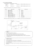
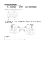
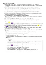
For connecting more than 1-m long cable, use a twisted cable.
・
For connecting more than 3-m long cable, use a shielded cable and always ground the shielded cable
to the ground terminal.
・
In addition, for connecting more than 30-m long cable or using outdoors, take special
countermeasures against noise.
・
Do not solder the wire or mount the press-fit terminal.
・
Be sure to turn OFF the WGA-910A before connecting cables.
・
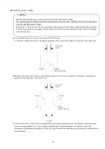
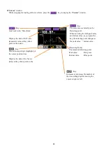
Despite executing of no-load ZERO or digital zero, a monitor output does not change.
It does not agree with a measured value which has been digitally processed.
・
A response frequency of the analog monitor output is same with the setting of the “Analog Filter.”
・
A monitor output is not electrically isolated from the internal circuitry. To connect it to an external
instrument, therefore use a shielded cable which is shorter than 3 meters. A longer cable is apt to be
affected by noise.
・
Do not short-circuit the terminals bMONITOR and -MONITOR.
Or, the WGA-910A may be damaged.
・
Do not input voltage from external.
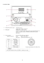
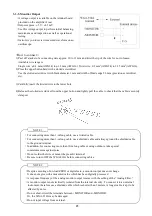
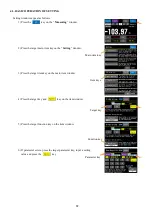
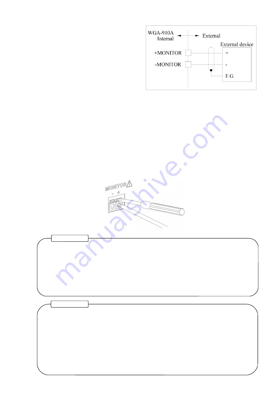
3-3-5. Monitior Output
・
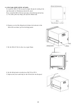
A voltage output is available on the terminal board
provided on the amplifier’s rear.
・
Outputs approx. ±5 V / ±3.2 mV.
・
Use this voltage output to perform initial balancing,
maintenance and inspection as well as operational
testing.
・
It also lets you to review measured waveform on an
oscilloscope.
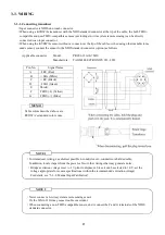
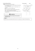
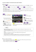
<How to connect>
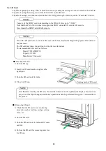
1) Peel off a jacket of a connecting wire approx. 10 to 11 mm and twist the tip of the wire for not to loosen.
Available wire range is
Single wire: φ0.4 mm (AWG24) to φ1.2 mm (AWG16), Twist wire: 0.2 mm
2
(AWG24) to 1.25 mm
2
(AWG16).
2) Press the upper button hard with a slotted screwdriver.
Use the slotted screwdriver with blade diameter 3 mm and width of blade edge 2.6 mm (precision screwdriver,
etc).
3) Carefully insert the twisted wire to the lower hole.
4) Release the slotted screwdriver from the upper button and lightly pull the cable to check that the cable is securely
clamped.
NOTE 1
NOTE 2
Содержание WGA-910A Series
Страница 112: ...108 7 OPERATION TIMING 7 1 CONTROL INPUT HOLD COMMAND RESET COMMAND ZERO COMMAND 7 1 1 Control Input ...
Страница 113: ...109 7 1 2 Block specified 7 1 3 Time specified ...
Страница 114: ...110 7 2 COMPARATOR OUTPUT 7 3 DELAY TIME BETWEEN INPUT AND OUTPUT Delay time between input RS output MAX 30 ms ...
Страница 145: ...141 11 2 DIMENSIONS Unit mm ...
Страница 150: ...146 Kyowa Electronic Instruments Co Ltd 3 5 1 Chofugaoka Chofu Tokyo 182 8520 Japan http www kyowa ei com ...


