82
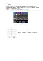
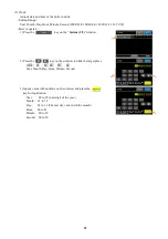
Satisfying trigger condition means starts
displaying the waveform when the
measured value passed the preset level in
the
Passed Level
and the measured
value passed as presetting in the
Level
Passed Way
.
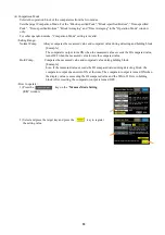
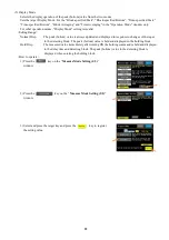
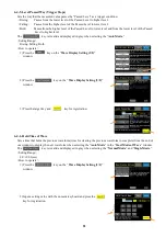
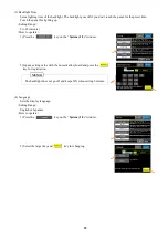
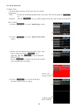
6-4-3. Start Mode of Wave (Trigger Mode)
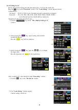
Sets a start mode (trigger mode) for displaying the waveform. Operations of modes are described as follows.
<Setting Range>
Auto Mode, Normal Mode, Single Mode
<How to operate>
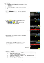
1) Press the
key on the “
Wave Display Setting (1/2)
”
window.
2) Press the target key and
key for registration.
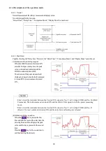
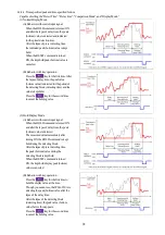
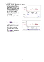
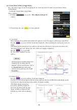
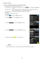
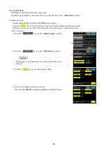
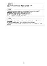
(1) Auto Mode
Starts displaying the waveform and automatically updates it even if the trigger conditions are not satisfied.
Press the
key or turn ON the “Waveform Command” of the control input for starting the waveform
display.
After displaying the waveform of one window to the end point of the X-axis, the waveform is held in the
“Waveform Holding Time” and then the next waveform is displayed repeatedly.
Press the
key or turn OFF
the “Waveform Command” for stop
loading.
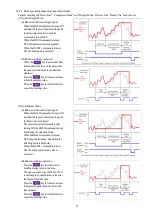
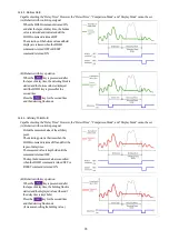
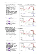
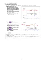
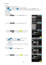
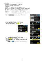
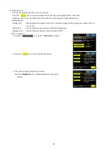
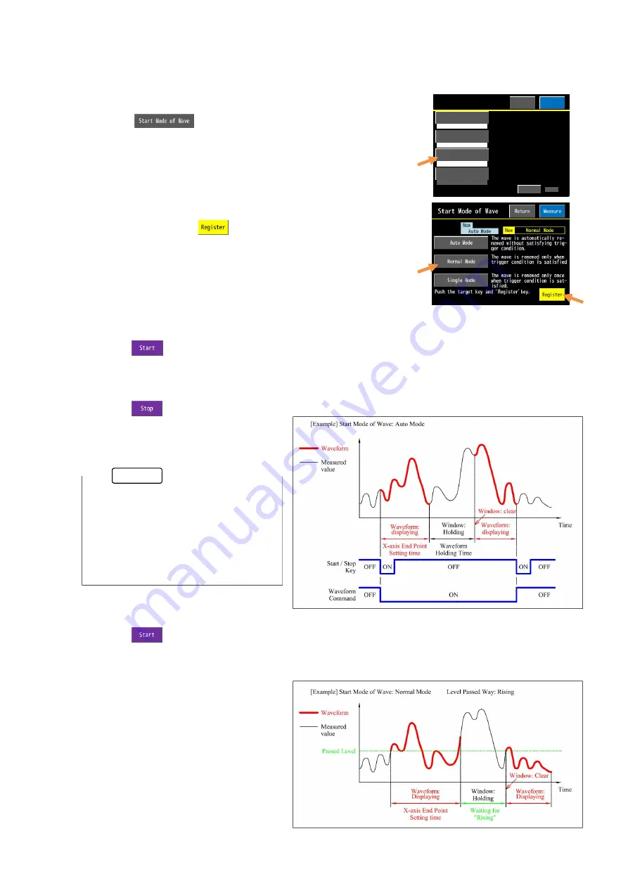
(2) Normal Mode
Press the
key or turn ON the “Waveform Command.”
The WGA-910A becomes trigger condition waiting mode (see the above MEMO) and starts displaying the
waveform only when the measured value satisfies the trigger condition.
After displaying the waveform of
one window until the end point of
the X-axis, the WGA-910A becomes
trigger condition waiting mode and
holds the waveform without updating
it.
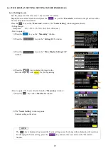
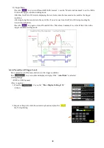
1 / 2
The level that measured value
passes for satisfying trigger
condition is set.
Next
1000.00kN
Auto Mode
0.00kN
The start and end point of Y-
axis are set.
The mode to start the wave
display is set.
Y-axis Setting
Start Mode of Wave
Passed Level
Wave Display Setting
The end point of X-axis(time)
is set.
10.0sec
Return
Measure
X-axis Setting
MEMO
Содержание WGA-910A Series
Страница 112: ...108 7 OPERATION TIMING 7 1 CONTROL INPUT HOLD COMMAND RESET COMMAND ZERO COMMAND 7 1 1 Control Input ...
Страница 113: ...109 7 1 2 Block specified 7 1 3 Time specified ...
Страница 114: ...110 7 2 COMPARATOR OUTPUT 7 3 DELAY TIME BETWEEN INPUT AND OUTPUT Delay time between input RS output MAX 30 ms ...
Страница 145: ...141 11 2 DIMENSIONS Unit mm ...
Страница 150: ...146 Kyowa Electronic Instruments Co Ltd 3 5 1 Chofugaoka Chofu Tokyo 182 8520 Japan http www kyowa ei com ...

