Hardware
48 of 70
Hardware R2.2.8 11.98.02 en
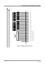
5.8
Peripheral connector X12 (optional)
X12
0V internal
+24V internal
57
+24V output 1--8
58
Output 2 (100mA)
75
0V output 1--8
93
Output 1 (100mA)
76
Output 3 (100mA)
94
Output 4 (100mA)
59
Output 5 (100mA)
77
Output 6 (100 mA)
95
Output 7 (100mA)
60
Output 8 (100 mA)
78
+24V output 9--16
79
Output 10 (100mA)
96
0V output 9--16
61
Output 9 (100mA)
97
Output 11 (100mA)
62
Output 12 (100mA)
80
Output 13 (100mA)
98
Output 14 (100mA)
63
Output 15 (100mA)
81
Output 16 (100mA)
15
Cross connection 1
16
Cross connection 2
17
Cross connection 3
18
Cross connection 4
33
Cross connection 5
34
Cross connection 6
35
Cross connection 7
36
Cross connection 8
52
Cross connection 9
53
Cross connection 10
54
Cross connection 11
Cr
os
s
co
nn
ec
tio
ns
to
X
11
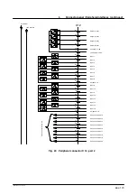
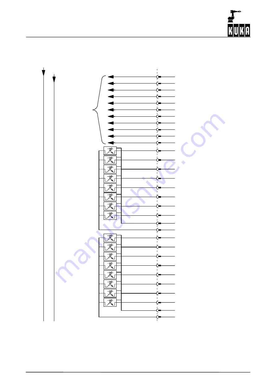
Fig. 28 Peripheral connector X12, part 1
If option X12 is used, the freely--programmable inputs/outputs on con-
nector X11 are omitted.
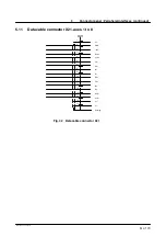
The cross connections are required for the routing of signals between
connectors X11 and X12. They have a maximum load capacity of 1 A
per cross connection.
Содержание KR C1
Страница 1: ...Hardware R2 2 8 11 98 02 en 1 of 70 SOFTWARE KR C1 Hardware Release 2 2...
Страница 30: ...Hardware 30 of 70 Hardware R2 2 8 11 98 02 en Fig 13 Circuit diagram X931 X604...
Страница 31: ...4 Individual axis switch off for external axes continued 31 of 70 Hardware R2 2 8 11 98 02 en Fig 14 Outputs...
Страница 32: ...Hardware 32 of 70 Hardware R2 2 8 11 98 02 en Fig 15 Inputs...
Страница 34: ...Hardware 34 of 70 Hardware R2 2 8 11 98 02 en...
Страница 35: ...35 of 70 Hardware R2 2 8 11 98 02 en...
Страница 55: ...55 of 70 Hardware R2 2 8 11 98 02 en...

