Hardware
16 of 70
Hardware R2.2.8 11.98.02 en
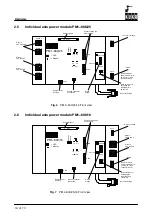
2.5
Individual axis power module PM1--600/25
X301H1
X301H2
X301M
X301L
X315
X316
X504
X508
X509
X505
SWITCH 1
SWITCH 2
BR
AKE
2
BR
AKE1
1Iw
2Iu
1Iu
2Iw
5V = Imax
PM1--600/25
= LED
= Monitor
X507
Motor 1
size A0 and A
Motor 1
size B and C
Motor 1
size D and E
Int. circuit voltage
Spare
(used on lowest
power module for re-
ceiving int. circuit
connector X315)
Int. circuit voltage
X3
15
Equipotential
bonding
Ground conductor
connection
Control signals
Control voltage and
driver supply
Brake
output
S3
S2
S1
Hook switches for
activating the
individual axis
switch--off
Fig. 6
PM 2--600/25/16 Front view
2.6
Individual axis power module PM1--600/16
X302M
X302L
X315
X316
X504
X508
X509
X505
SWITCH 1
SWITCH 2
BR
AKE
2
BR
AKE1
1Iw
2Iu
1Iu
2Iw
5V = Imax
PM1--600/16
= LED
= Monitor
X507
Motor 2
size B and C
Motor 2
size D and E
Int. circuit voltage
Spare
(used on lowest
power module for re-
ceiving int. circuit
connector X315)
Int. circuit voltage
X3
15
Equipotential
bonding
Ground conductor
connection
Control signals
Control voltage and
driver supply
Brake
output
S3
S2
S1
Hook switches for
activating the
individual axis
switch--off
Fig. 7
PM 2--600/25/16 Front view
Содержание KR C1
Страница 1: ...Hardware R2 2 8 11 98 02 en 1 of 70 SOFTWARE KR C1 Hardware Release 2 2...
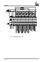
Страница 30: ...Hardware 30 of 70 Hardware R2 2 8 11 98 02 en Fig 13 Circuit diagram X931 X604...
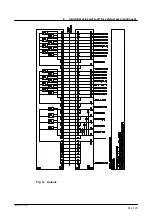
Страница 31: ...4 Individual axis switch off for external axes continued 31 of 70 Hardware R2 2 8 11 98 02 en Fig 14 Outputs...
Страница 32: ...Hardware 32 of 70 Hardware R2 2 8 11 98 02 en Fig 15 Inputs...
Страница 34: ...Hardware 34 of 70 Hardware R2 2 8 11 98 02 en...
Страница 35: ...35 of 70 Hardware R2 2 8 11 98 02 en...
Страница 55: ...55 of 70 Hardware R2 2 8 11 98 02 en...


