7
Resolver--to--Digital Converter (RDC) (continued)
69 of 70
Hardware R2.2.8 11.98.02 en
7.7.2.4 RDC calibration
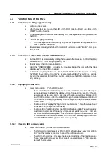
RDC calibration is necessary after a motor has been replaced. During calibration, the A/D
converter and EEPROM of the RDC can be tested. All RDCs supplied by KUKA, including
replacement RDCs, are ready--calibrated.
G
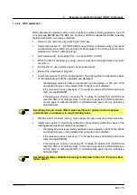
Return to the main menu by pressing the ”Esc” key.
G
Select menu option ”A” (Set RDC offset and symmetry to default values); this option
automatically sets the RDC sine and cosine offset values to ”0” and the sine and cosine
calibration to ”20000” (default setting).
G
Quit ”dserdw.exe” by pressing ”Esc” and open KR C1 (ICON).
G
When the KR C1 controller is running, all axes must travel through at least one motor
revolution.
G
Exit the KR C1 user interface again, as described above.
G
Restart the ”dserdw.exe” program.
G
Select menu option ”3” (Offset compensation); the existing offset compensation values
of the individual axes will be calculated and displayed:
--
the displayed values for offset compensation can be between --1500 and +1600
and depend largely on the installed A/D converter and multiplexer;
--
if the values are correct, press key ”Y” to accept the values of the RDC and to load
them into the EEPROM.
--
if the values are incorrect, press key ”N” to refuse the values from the RDC and
reset the RDC to its default values. In this case, repeat step 5 (RDC calibration)
and try again to calibrate the RDC. If calibration fails again, there is probably a
hardware fault.
Deviating sine and cosine offset values lead to poor quality control response
and therefore, on occasion, to rough running noise.
G
With the KR C1 controller running, move all axes through at least one motor revolution.
G
Select menu option ”4” (Symmetry calibration): the symmetry calibration values of the
individual axes will be calculated and displayed:
--
the displayed values for symmetry calibration can be between --18000 and +23000
and depend largely on the installed A/D converter and multiplexer.
--
if the values are correct, press key ”Y” to accept the values of the RDC and to load
them into the EEPROM.
--
if the values are incorrect, press key ”N” to refuse the values from the RDC and
reset the RDC to its default values. In this case, repeat step 5 (RDC calibration)
and try again to calibrate the RDC. If calibration fails again, there is probably a
hardware fault.
Deviating symmetry calibration values generally lead to the error ”Encoder cable
failure axis X”.
Содержание KR C1
Страница 1: ...Hardware R2 2 8 11 98 02 en 1 of 70 SOFTWARE KR C1 Hardware Release 2 2...
Страница 30: ...Hardware 30 of 70 Hardware R2 2 8 11 98 02 en Fig 13 Circuit diagram X931 X604...
Страница 31: ...4 Individual axis switch off for external axes continued 31 of 70 Hardware R2 2 8 11 98 02 en Fig 14 Outputs...
Страница 32: ...Hardware 32 of 70 Hardware R2 2 8 11 98 02 en Fig 15 Inputs...
Страница 34: ...Hardware 34 of 70 Hardware R2 2 8 11 98 02 en...
Страница 35: ...35 of 70 Hardware R2 2 8 11 98 02 en...
Страница 55: ...55 of 70 Hardware R2 2 8 11 98 02 en...


