Hardware
64 of 70
Hardware R2.2.8 11.98.02 en
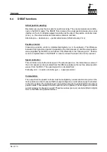
EMT interface:
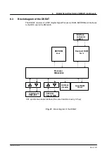
The two channels of the EMT are read as binary inputs and transmitted in serial mode to the
DSEAT together with the actual values and motor temperatures.
A Lemosa (5--pin) connector is used for the EMT interface.
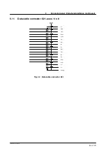
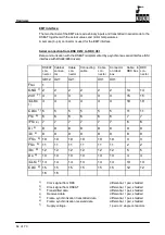
Serial connection from DSE X812 to RDC X31
Data communication with the DSEAT is implemented by a synchronous serial interface (SSI
interface with RS422/485 drivers).
DSEAT
con-
nector
Cabinet
connec-
tor
Cable
con-
nector
Connecting
cable
Cable
con-
nector
Connector
on robot
box
Cable in
RDC box
RDC
con-
nector
X812 X21
X21
X31
X31
Frei
1
GND
7)
2
2
2
2
2
2
14
14
24V
7)
3
3
3
3
3
3
15
15
/CLKo
1)
4
4
4
4
4
4
10
10
CLKo
1)
5
5
5
5
5
5
11
11
FSi
6)
6
6
6
6
6
6
7
7
/FSi
6)
7
7
7
7
7
7
6
6
Di
4)
8
8
8
8
8
8
9
9
/Di
4)
9
9
9
9
9
9
8
8
/FSo
5)
10
10
10
10
10
10
3
3
FSo
5)
11
11
11
11
11
11
2
2
/Do
3)
12
12
12
12
12
12
5
5
Do
3)
13
13
13
13
13
13
4
4
/CLKi
2)
14
14
14
14
14
14
13
13
CLKi
2)
15
15
15
15
15
15
12
12
16
16
1)
Clock signal from RDC
differential, 1 pair, shielded
2)
Clock signal from DSEAT
differential, 1 pair, shielded
3)
Transmitted data
differential, 1 pair, shielded
4)
Received data
differential, 1 pair, shielded
5)
Frame synchronization transmitted data
differential, 1 pair, shielded
6)
Frame synchronization received data
differential, 1 pair, shielded
7)
Supply voltage
1 pair or 2 single conductors
Содержание KR C1
Страница 1: ...Hardware R2 2 8 11 98 02 en 1 of 70 SOFTWARE KR C1 Hardware Release 2 2...
Страница 30: ...Hardware 30 of 70 Hardware R2 2 8 11 98 02 en Fig 13 Circuit diagram X931 X604...
Страница 31: ...4 Individual axis switch off for external axes continued 31 of 70 Hardware R2 2 8 11 98 02 en Fig 14 Outputs...
Страница 32: ...Hardware 32 of 70 Hardware R2 2 8 11 98 02 en Fig 15 Inputs...
Страница 34: ...Hardware 34 of 70 Hardware R2 2 8 11 98 02 en...
Страница 35: ...35 of 70 Hardware R2 2 8 11 98 02 en...
Страница 55: ...55 of 70 Hardware R2 2 8 11 98 02 en...


