5
Connector panel / Peripheral interfaces (continued)
49 of 70
Hardware R2.2.8 11.98.02 en
X12
0V internal
+24V internal
70
Cross connection 12
71
Cross connection 13
72
Cross connection 14
88
Cross connection 15
89
Cross connection 16
90
Cross connection 17
106
Cross connection 18
107
Cross connection 19
108
Cross connection 20
Cr
os
s
co
nn
ec
tio
ns
to
X
11
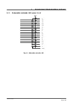
99
0V input 1--8
82
Input 2
64
Input 1
100
Input 3
65
Input 4
101
Input 6
84
Input 8
83
Input 5
66
Input 7
102
0V input 9--16
85
Input 10
67
Input 9
103
Input 11
68
Input 12
104
Input 14
87
Input 16
86
Input 13
69
Input 15
55
+24V output 17--20
56
Output 18 (2A)
73
0V output 17--20
91
Output 17 (2A)
74
Output 19 (2A)
92
Output 20 (2A)
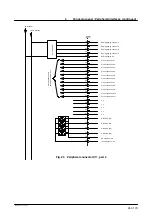
Fig. 29 Peripheral connector X 12, part 2
Содержание KR C1
Страница 1: ...Hardware R2 2 8 11 98 02 en 1 of 70 SOFTWARE KR C1 Hardware Release 2 2...
Страница 30: ...Hardware 30 of 70 Hardware R2 2 8 11 98 02 en Fig 13 Circuit diagram X931 X604...
Страница 31: ...4 Individual axis switch off for external axes continued 31 of 70 Hardware R2 2 8 11 98 02 en Fig 14 Outputs...
Страница 32: ...Hardware 32 of 70 Hardware R2 2 8 11 98 02 en Fig 15 Inputs...
Страница 34: ...Hardware 34 of 70 Hardware R2 2 8 11 98 02 en...
Страница 35: ...35 of 70 Hardware R2 2 8 11 98 02 en...
Страница 55: ...55 of 70 Hardware R2 2 8 11 98 02 en...


