Hardware
14 of 70
Hardware R2.2.8 11.98.02 en
2.1
Basic module PM0--600
The PM0--600 incorporates:
G
Clocked, controlled low voltage supply for the following modules
-- Periphery (27 V DC / 6 A + 4 A, individually fused)
-- PC (27 V DC / 6 A, backed up by external batteries)
-- Equipment within the cabinet (27 V DC / 4 A)
-- Holding brake for motors (26.5 V DC / 7.5 A)
-- Lead battery for backing up the PC (26.8 V DC) incl. charging and discharging control
-- PM0--600 logic (15 V DC, --15 V DC, +5 V DC, with back--up)
-- PM1(2)--600 drivers (16 V AC / 100 kHz)
G
600 V supply module for output stages incl.
-- Main contactor and starting circuit
-- Mains overvoltage limiter
-- Intermediate circuit rectifier (600 V DC / 4 kW)
-- Ballast circuit 800 W (can be extended to 2 kW)
-- High--speed discharge of intermediate circuit
-- Temperature monitoring
-- Suppression elements
-- Interface with safety module (FE201)
G
Logic module incl.
-- Bidirectional interface for parallel data transmission from/to DSEAT with parity check
-- Current controller and pulse width modulation
-- Logic operations (e.g. drive enables, brake control)
-- Fault detection:
brake fault, overvoltage, undervoltage, battery charge,
overtemperature, motor overcurrent, current controller limitation,
transmission error, sumcheck error
-- Detection and signalling of: motor connector assignment, ready for operation
2.2
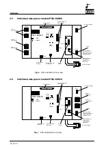
1--axis power module PM 1--600/.. , 2--axis power module PM
2--600/25--16
The power modules incorporate:
G
IGBT servo output stages for 1 or 2 robot axes or external axes incl.
-- Intermediate circuit electrolytic capacitors
-- Driver boards with integrated short--circuit protection of the output stage
-- Potential--free motor current measurement
-- Short--circuit braking relay
-- Power adaptation to motor sizes via motor connector selection
-- Monitoring of heat sink temperature
-- Individual axis switch--off
Содержание KR C1
Страница 1: ...Hardware R2 2 8 11 98 02 en 1 of 70 SOFTWARE KR C1 Hardware Release 2 2...
Страница 30: ...Hardware 30 of 70 Hardware R2 2 8 11 98 02 en Fig 13 Circuit diagram X931 X604...
Страница 31: ...4 Individual axis switch off for external axes continued 31 of 70 Hardware R2 2 8 11 98 02 en Fig 14 Outputs...
Страница 32: ...Hardware 32 of 70 Hardware R2 2 8 11 98 02 en Fig 15 Inputs...
Страница 34: ...Hardware 34 of 70 Hardware R2 2 8 11 98 02 en...
Страница 35: ...35 of 70 Hardware R2 2 8 11 98 02 en...
Страница 55: ...55 of 70 Hardware R2 2 8 11 98 02 en...


