5
Connector panel / Peripheral interfaces (continued)
39 of 70
Hardware R2.2.8 11.98.02 en
5.3
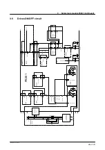
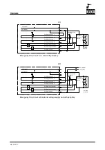
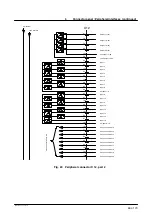
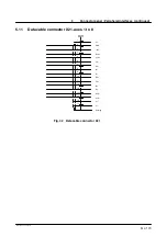
Emergency Stop circuit
The following examples show how the robot Emergency Stop circuit can be linked to other
robots or with the periphery.
37
1
19
2
3
20
21
4
22
40
0V internal
24V internal
Em. Stop channel 1 I
Em. Stop channel 1 O
Em. Stop channel 2 I
Em. Stop channel 2 O
Em. Stop relay channel 1
Em. Stop relay channel 2
Em. Stop relay 0V
Emergency Stop circuit for a robot without periphery
X11
37
1
19
2
3
20
21
4
22
40
0V internal
24V internal
Em. Stop channel 1 I
Em. Stop channel 1 O
Em. Stop channel 2 I
Em. Stop channel 2 O
Em. Stop relay channel 1
Em. Stop relay channel 2
Em. Stop relay 0V
Emergency Stop circuit for two robots without periphery
X11
37
1
19
2
3
20
21
4
22
40
0V internal
24V internal
Em. Stop channel 1 I
Em. Stop channel 1 O
Em. Stop channel 2 I
Em. Stop channel 2 O
Em. Stop relay channel 1
Em. Stop relay channel 2
Em. Stop relay 0V
Содержание KR C1
Страница 1: ...Hardware R2 2 8 11 98 02 en 1 of 70 SOFTWARE KR C1 Hardware Release 2 2...
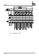
Страница 30: ...Hardware 30 of 70 Hardware R2 2 8 11 98 02 en Fig 13 Circuit diagram X931 X604...
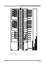
Страница 31: ...4 Individual axis switch off for external axes continued 31 of 70 Hardware R2 2 8 11 98 02 en Fig 14 Outputs...
Страница 32: ...Hardware 32 of 70 Hardware R2 2 8 11 98 02 en Fig 15 Inputs...
Страница 34: ...Hardware 34 of 70 Hardware R2 2 8 11 98 02 en...
Страница 35: ...35 of 70 Hardware R2 2 8 11 98 02 en...
Страница 55: ...55 of 70 Hardware R2 2 8 11 98 02 en...

