6
Digital Servo Electronics (DSEAT) (continued)
59 of 70
Hardware R2.2.8 11.98.02 en
6.5
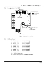
Configuration of the DSEAT
Boot from dual port RAM
Watchdog LEDs (at rear)
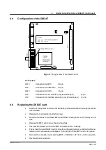
Fig. 38
(Rough) View of the DSEAT card
Connectors
X810
Connection for MFC
50--pin
X811
Connection for PM6--600
40--pin
X812
Connection for RDC
15--pin
JP2:
Connection for test adaptor (only for developers)
6--pin
JP3:
Connection for interface emulator (only for developers)
12--pin
6.6
Replacing the DSEAT card
G
Switch off the system and wait until the battery--backed shutdown storage procedure
is terminated.
G
Release the card retainer (butterfly screw)
G
Disconnect all lines to the KVGA, MFC and DSEAT and lay them out of the way on one
side.
G
Release the MFC and remove the card carefully.
G
Unscrew the DSEAT card on the MFC and disconnect it carefully.
G
Check that the new DSEAT card is correctly configured (jumper), valid (date of manu-
facture) and mechanically undamaged. Then plug it into the MFC and fix it in place.
G
Reinsert the complete card assembly (MFC + DSEAT) in AT slot 1 and fix in position.
G
Reconnect all connections.
Содержание KR C1
Страница 1: ...Hardware R2 2 8 11 98 02 en 1 of 70 SOFTWARE KR C1 Hardware Release 2 2...
Страница 30: ...Hardware 30 of 70 Hardware R2 2 8 11 98 02 en Fig 13 Circuit diagram X931 X604...
Страница 31: ...4 Individual axis switch off for external axes continued 31 of 70 Hardware R2 2 8 11 98 02 en Fig 14 Outputs...
Страница 32: ...Hardware 32 of 70 Hardware R2 2 8 11 98 02 en Fig 15 Inputs...
Страница 34: ...Hardware 34 of 70 Hardware R2 2 8 11 98 02 en...
Страница 35: ...35 of 70 Hardware R2 2 8 11 98 02 en...
Страница 55: ...55 of 70 Hardware R2 2 8 11 98 02 en...

