Hardware
36 of 70
Hardware R2.2.8 11.98.02 en
5
Connector panel / Peripheral interfaces
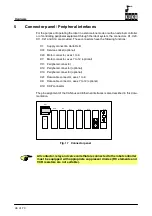
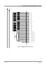
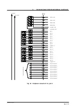
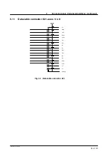
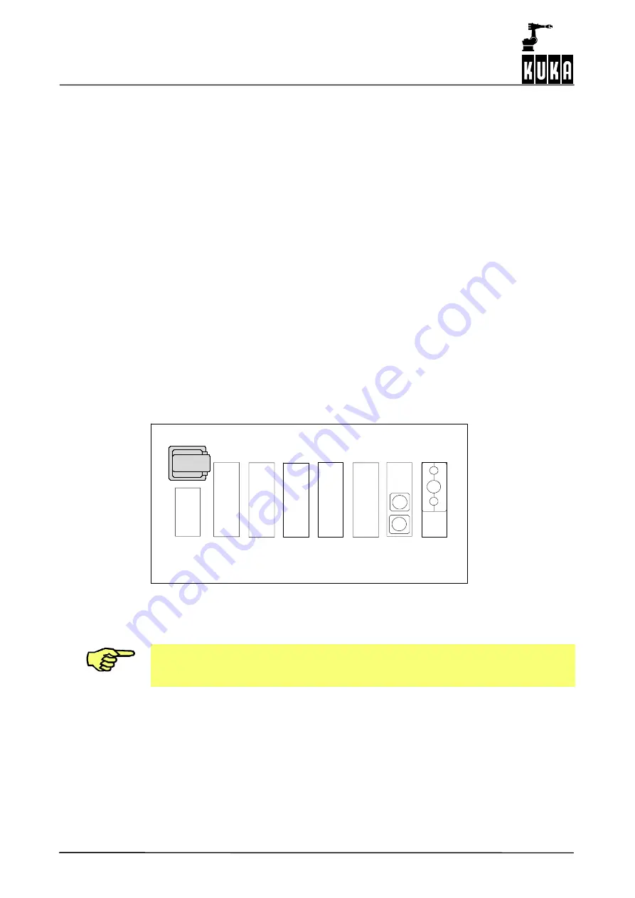
For the purpose of operating the robot in a stand--alone mode or with an external controller,
or of controlling peripheral equipment through the robot system, the connectors X1, X20,
X11, X21 and X19 are provided. These connectors have the following functions:
X1:
Supply connection Han6 HsB
X01: Service socket (optional)
X20: Motor connector, axes 1 to 6
X7:
Motor connector, axes 7 to 12 (optional)
X11: Peripheral connector
X12: Peripheral connector (optional)
X13: Peripheral connector (optional)
X21: Data cable connector, axes 1 to 8
X8:
Data cable connector, axes 7 to 12 (optional)
X19: KCP connector
The pin assignment of the CAN bus and Ethernet interfaces is also described in this docu-
mentation.
X01
X1
X20
X11
X12
X21
X13
X19
X8
Fig. 17 Connector panel
X7
All contactor, relay and valve coils that are connected to the robot controller
must be equipped with appropriate suppressor diodes (RC elements and
VCR resistors are not suitable).
Содержание KR C1
Страница 1: ...Hardware R2 2 8 11 98 02 en 1 of 70 SOFTWARE KR C1 Hardware Release 2 2...
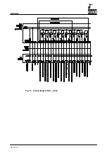
Страница 30: ...Hardware 30 of 70 Hardware R2 2 8 11 98 02 en Fig 13 Circuit diagram X931 X604...
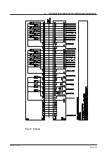
Страница 31: ...4 Individual axis switch off for external axes continued 31 of 70 Hardware R2 2 8 11 98 02 en Fig 14 Outputs...
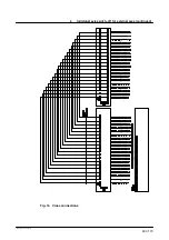
Страница 32: ...Hardware 32 of 70 Hardware R2 2 8 11 98 02 en Fig 15 Inputs...
Страница 34: ...Hardware 34 of 70 Hardware R2 2 8 11 98 02 en...
Страница 35: ...35 of 70 Hardware R2 2 8 11 98 02 en...
Страница 55: ...55 of 70 Hardware R2 2 8 11 98 02 en...


