Hardware
60 of 70
Hardware R2.2.8 11.98.02 en
6.7
Function test of the DSEAT card
6.7.1
Visual inspection of the LEDs
G
Switch on the system.
G
After initialization (DSE runup), check that the LED on the DSEAT is flashing (at inter-
vals of 0.5 sec.) and that the watchdog LED on the power module and the LED on the
RDC are lit.
6.7.2
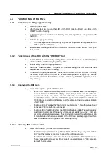
Function test of the DSEAT with the ”DSERDW” diagnostic tool
G
Quit the KR C1 user interface by clicking the mouse on the status bar. Confirm the dialog
window with the ”ICON” entry by clicking ”OK”.
G
Minimize any other running applications.
G
Start the ”DSERDW.EXE” program (by double--clicking the icon with the label
”dserdw.exe” on the WIN95 desktop).
G
In the main program (dserdw.exe), check that the DSE controller program is running;
the ”DSE 125
μ
s Interrupt Counter” is incremented by DSEAT every 125
μ
s and dis-
played in hexadecimal format. If the counter is stationary, the DSE program is not run-
ning correctly.
G
Select menu item ”7” (Check RDC communication).
--
The 1st word (command sent by DSE to RDC) should always vary from 4000 to
4007 (but the display is too slow to show the individual values).
--
The 2nd to 9th word (axis X) shows the resolver positions of the individual axes.
These values will normally vary: if the value of the relevant axes is ”000”, an enco-
der fault has occurred.
--
The 10th word (value) is the motor temperature of axes 1--8, requested by the DSE
in the command. Normally, this value should vary.
--
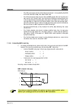
The 11th word (error) shows the error bits and EMT signals. Bits 0 to 7 are the error
bits of axes 1 to 8. If a bit is ”high”, a sensor error has been recorded for the axis.
In the component test stand (6 axes), this value is normally set to ”00C0” (hex),
corresponding to ”0000 0000 1100 0000” (binary). This value recognizably repre-
sents the error bits of axis 7 and axis 8 (because these axes are not connected).
Bits 8 and 9 are the EMT signals (see ”EMT mastering”).
--
The 12th word (Chksum) is the checksum for all the data. Normally, this value
should vary.
--
The ”Communication error status” indicates whether more than 3 consecutive
transmissions have failed. If so, the status value is 1. Under normal conditions,
this value is ”0000”. If the status is 1, DSEAT--RDC communication is disrupted
by fault condition(s).
--
The ”Communication error counter” counts all faulty transmissions; under normal
conditions, this value too should be ”0000”.
Содержание KR C1
Страница 1: ...Hardware R2 2 8 11 98 02 en 1 of 70 SOFTWARE KR C1 Hardware Release 2 2...
Страница 30: ...Hardware 30 of 70 Hardware R2 2 8 11 98 02 en Fig 13 Circuit diagram X931 X604...
Страница 31: ...4 Individual axis switch off for external axes continued 31 of 70 Hardware R2 2 8 11 98 02 en Fig 14 Outputs...
Страница 32: ...Hardware 32 of 70 Hardware R2 2 8 11 98 02 en Fig 15 Inputs...
Страница 34: ...Hardware 34 of 70 Hardware R2 2 8 11 98 02 en...
Страница 35: ...35 of 70 Hardware R2 2 8 11 98 02 en...
Страница 55: ...55 of 70 Hardware R2 2 8 11 98 02 en...

